Table of Contents
Advertisement
Quick Links
Series K . K40-R
Meter for process signals
PANEL MEtERS
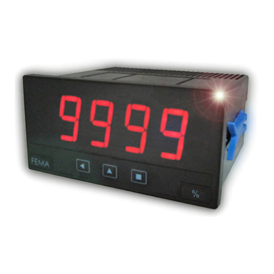
Panel meter for potentiometers and ratiometric signals, with 20 mm digit height. Provides 5 Vdc ex-
citation voltage or external excitation voltage. Standard 96 x 48 mm size (1/8 DIN). Reading with 4
digit display. Segment linearization, fast access to alarm setpoints, 'on power up' function, 'measure'
function, configurable reading brightness. Universal AC and DC power. Up to 3 optional modules for
output and control (relays, analog outputs, Modbus RTU communications, RS-485 ASCII, RS-232, ...)
3566r03
ELECTRONICS
FOR
PANEL METERS . SIGNAL CONVERTERS . LARGE DISPLAYS
Tel. (+34) 93.729.6004 info@fema.es
User's Manual
INDUSTRIAL
AUTOMATION
www.fema.es
Advertisement
Table of Contents

Related Manuals for Fema Electronica K40-R


Summary of Contents for Fema Electronica K40-R
- Page 1 ELECTRONICS INDUSTRIAL AUTOMATION PANEL METERS . SIGNAL CONVERTERS . LARGE DISPLAYS Series K . K40-R Meter for process signals PANEL MEtERS Panel meter for potentiometers and ratiometric signals, with 20 mm digit height. Provides 5 Vdc ex- citation voltage or external excitation voltage. Standard 96 x 48 mm size (1/8 DIN). Reading with 4 digit display.
-
Page 2: Table Of Contents
Index 1. Panel meter K40-R ..... . . 2 1.11 Full configuration menu ....12 1.1 How to order . -
Page 3: Front View
FEMA ELECTRÓNICA . Series K . K40-R 1.2 Front view 1.5 Signal connections Alarms Connections for potentiometers and ratiometric sensors 1 2 3 Vexc. +5V Signal Logo Units Common Button ‘LE’ Button ‘UP’ Button ‘SQ’ Connections for potentiometers and ratiometric, in passive mode ‘Fast access‘... -
Page 4: Technical Specifications
FEMA ELECTRÓNICA . Series K . K40-R 1.7 Technical specifications Digits Functions included Section number of digits 7 segments led Segment linearization up to 20 segments 1.10.5 color Display filters recursive 1.10.4 digit height 20 mm steps fixed digits Reading... -
Page 5: How To Operate The Menus
FEMA ELECTRÓNICA . Series K . K40-R 1.8 How to operate the menus The instrument has two menus accessible to the user : Example of operation inside the ‘configuration menu’. ‘Configuration menu’ (key SQ) (<) 1. The SQ (<) key enters into the ‘Fast access’... -
Page 6: Configuration Menu
FEMA ELECTRÓNICA . Series K . K40-R 1.10 Configuration menu 1.10.1 Initial set-up Press ‘SQ’ (<) for 1 second to access the ‘configuration menu’. For a description on how to operate inside the menus see sec- tion 1.8. For a full vision of the ‘configuration menu’ structure To configure the initial set up of the instrument, select the type of see section 1.11. -
Page 7: Alarms
FEMA ELECTRÓNICA . Series K . K40-R 1.10 Configuration menu (cont.) 1.10.3 Alarms The ‘Alarms’ (‘ALr’) menu configures the independent activation of Alarms up to 3 relay outputs, installed with the R1 optional modules (see section 2.1). For outputs up to 4 and 6 relays, see special modules R2, R4 and R6 at section 2.6. -
Page 8: Display Filters
FEMA ELECTRÓNICA . Series K . K40-R 1.10 Configuration menu (cont.) 1.10.4 Display filters The instrument provides several functions to personalize the reading Display Fixed digits Fix digits of the display values • the ‘Fixed Digits’ (‘FIX.d’) allows to fix each digit to a fixed value. -
Page 9: Segment Linearization
FEMA ELECTRÓNICA . Series K . K40-R 1.10 Configuration menu (cont.) 1.10.5 Segment linearization The ‘Segment Linearization’ (‘S.LIn’) menu provides up to 20 seg- Tools ments to linearize non-linear signals. • at the ‘Number of segments’ (‘nuM’) parameter, select the num-... -
Page 10: Menu 'On Power Up
FEMA ELECTRÓNICA . Series K . K40-R 1.10 Configuration menu (cont.) 1.10.8 Menu ‘On Power Up’ The ‘On Power Up’ (‘on.Pu’) menu configures functions to apply at Tools start-up. It applies only to instrument restart after power loss. It does not apply to instrument restart due to change in configuration. -
Page 11: Factory Reset
FEMA ELECTRÓNICA . Series K . K40-R 1.10 Configuration menu (cont.) Tools 1.10.11 Factory reset Factory reset At the ‘Factory reset’ (‘FAct’) menu, select ‘yes’ to load the default factory configuration for the instrument (see section 1.15). Version 1.10.12 Firmware version Minimum The ‘Version’... -
Page 12: Full Configuration Menu
FEMA ELECTRÓNICA . Series K . K40-R 1.11 Full configuration menu Press ‘SQ’ (<) for 1 second to access the ‘Configuration menu’. See section for a description of each menu entry. 1.10 Relay inverted Ratiometric transducer Input Locked alarm Potentiometer between 200 Ohm and 5 KOhms Potentiometer <5 MOhms... - Page 13 FEMA ELECTRÓNICA . Series K . K40-R 1.11 Full configuration menu (cont.) No function Key LE Tools Alarm unlock Segment Number Value 2 to 20 linearization of segments Scaling Input 0 Password Display 0 Factory reset Input 1 Display 1...
-
Page 14: To Access The Instrument
FEMA ELECTRÓNICA . Series K . K40-R 1.12 To access the instrument You may need to access the inside of the instrument to add or re- place internal modules. Use a flat screwdriver to unlock the upper clips marked with ‘A’. Then unlock the lower clips marked with ‘B’ and remove the front cover. -
Page 15: Precautions On Installation
FEMA ELECTRÓNICA . Series K . K40-R 1.14 Precautions on installation General recommendations for electrical installations apply, and for proper Risk of electrical shock. Instrument terminals can be connected functionality we recommend : if possible, install the instrument far from to dangerous voltage. -
Page 16: Output And Control Modules
FEMA ELECTRÓNICA . Series K . K40-R 2. Output and control modules 2.1 Module R1 2.2 Module AO The R1 module provides 1 relay output to K Series panel meters. Up The AO module provides 1 analog output with 4/20 mA or 0/10 Vdc to a maximum of 3 R1 modules can be installed in a single instru- configurable output range. -
Page 17: Module Rtu
FEMA ELECTRÓNICA . Series K . K40-R 2.3 Module RTU 2.4 Module S4 The RTU module provides a Modbus RTU communications module The S4 module provides a RS-485 communications module for K for K Series of panel meters. The RTU module implements function Series of panel meters. -
Page 18: Module S2
FEMA ELECTRÓNICA . Series K . K40-R 2.5 Module S2 2.6 Modules R2, R4, R6 The S2 module provides a RS-232 communications module for K The R2, R4 and R6 modules provide 2, 4 and 6 relay outputs for K Series of panel meters. - Page 19 FEMA ELECTRÓNICA . Series K . K40-R...
-
Page 20: Other Options
FEMA ELECTRÓNICA . Series K . K40-R 3. Other options 3.1 Option NBT Instruments without front key- pad. To configure the instrument, remove the meter from the panel and remove the front filter. Inter- nal press buttons for configuration are accessible. Optionally, request... -
Page 21: Accessories
FEMA ELECTRÓNICA . Series K . K40-R 4. Accessories 4.1 THM benchtop housing 4.4 WME housing Benchtop housing for Series M Wall mount housing. Together and Series K of panel meters. with the KIP protector, offer a Handle with three selectable posi- full IP65 protection. - Page 22 FEMA ELECTRÓNICA . Series K . K40-R Notes...
- Page 23 FEMA ELECTRÓNICA . Series K . K40-R Notes...
- Page 24 Panel meters Panel meters Signal converters Standard 96 x 48 mm Miniature 48 x 24 mm Panel meters Large format meters Bar meters Compact 72 x 36 mm ‘Customized’ Isolators Low cost instruments MODBUS TrueRMS TrueRMS RS-485 Load FEMA ELECTRÓNICA, S.A. Altimira 14 - Pol.
Need help?
Do you have a question about the K40-R and is the answer not in the manual?
Questions and answers