Table of Contents
Advertisement
Quick Links
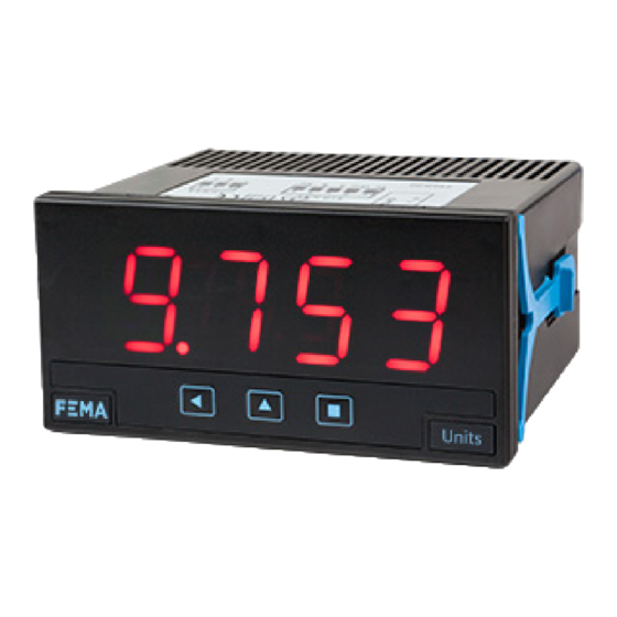
Series K . K40-A
AC Voltmeter and AC Ammeter
PANEL METERS
AC voltmeter and AC ammeter for panel mount, with 20 mm digit height. Scalable reading. Measure
in True RMS. Measure up to 600 Vac and up to 5 Aac. Measure category CAT-II and CAT-III. Selectable
signal coupling mode 'AC' or 'AC+DC'. Standard 96 x 48 mm size (1/8 DIN). Reading with 4 digit dis-
play. Fast access to alarm setpoints, 'on power up' function, 'measure' function, configurable reading
brightness. Universal AC and DC power. Up to 3 optional modules for output and control (relays, tran-
sistor, control SSR, analog outputs, Modbus RTU communications, RS-485 ASCII, RS-232, ...)
3632r04
ELECTRONICS
FOR
PANEL METERS . SIGNAL CONVERTERS . LARGE DISPLAYS
Tel. (+34) 93.729.6004 info@fema.es
User's Manual
INDUSTRIAL
AUTOMATION
www.fema.es
Advertisement
Table of Contents

Subscribe to Our Youtube Channel
Related Manuals for Fema Electronica K K40-A Series


Summary of Contents for Fema Electronica K K40-A Series
- Page 1 User’s Manual ELECTRONICS INDUSTRIAL AUTOMATION PANEL METERS . SIGNAL CONVERTERS . LARGE DISPLAYS Series K . K40-A AC Voltmeter and AC Ammeter PANEL METERS AC voltmeter and AC ammeter for panel mount, with 20 mm digit height. Scalable reading. Measure in True RMS. Measure up to 600 Vac and up to 5 Aac. Measure category CAT-II and CAT-III. Selectable signal coupling mode ‘AC’...
-
Page 2: Table Of Contents
FEMA ELECTRÓNICA . Series K . K40-A 1. Panel meter K40-A AC voltmeter and AC ammeter, size 96 mm (1/8 DIN) , with 20 mm digit height Panel meter 96 x 48 mm (1/8 DIN) for AC voltage and AC current Front protection IP65. -
Page 3: Front View
FEMA ELECTRÓNICA . Series K . K40-A 1.2 Front view 1.5 Signal connections - AC voltage Alarms To configure the voltage AC measure, select the jumper for the de- sired scale as indicated in the table below. Then activate the selected scale in the configuration menu (see section 1.12.1) and connect the input signal to the signal terminals. -
Page 4: Technical Specifications
FEMA ELECTRÓNICA . Series K . K40-A 1.7 Technical specifications Digits Power number of digits power ‘H’ 85 a 265 Vac/dc 7 segments led power ‘L’ 11 a 60 Vdc y 24/48 Vac color isolation* 2500 Veff with power ‘H’ digit height 20 mm 1500 Veff with power ‘L’ *all units tested during 60 seconds Reading consumption... -
Page 5: Mechanical Dimensions (Mm)
FEMA ELECTRÓNICA . Series K . K40-A 1.7 Technical specifications (cont.) 1.8 Mechanical dimensions (mm) Functions included Section ‘Fast access’ 1.12.5 ‘On Power Up’ 1.12.7 ‘Field correction’ yes, high and low signals 1.12.2 Alarms double setpoints 1.12.3 Panel activation delays cut-out deactivation delays hysteresis... -
Page 6: How To Operate The Menus
FEMA ELECTRÓNICA . Series K . K40-A 1.10 How to operate the menus The instrument has two menus accessible to the user : Example of operation inside the ‘configuration menu’. ‘Configuration menu’ (key SQ) (<) 1. The SQ (<) key enters into the ‘Fast access’... -
Page 7: Configuration Menu
FEMA ELECTRÓNICA . Series K . K40-A 1.12 Configuration menu 1.12.1 Initial set-up Press ‘SQ’ (<) for 1 second to access the ‘configuration menu’. For a description on how to operate inside the menus see section 1.10 . For a full vision of the ‘configuration menu’ structure see To configure the initial set up of the instrument, select the measure 1.13 section... -
Page 8: Alarms
FEMA ELECTRÓNICA . Series K . K40-A 1.10 Configuration menu (cont.) 1.12.3 Alarms The ‘Alarms’ (‘ALr’) menu configures the independent activation of Alarms up to 3 relay outputs (or transistor or SSR control), installed with the R1 (or T1 or SSr) optional modules (see section 2.1). For outputs up to 4 and 6 relays, see special modules R2, R4 and R6 at section 2.6. -
Page 9: Display Filters
FEMA ELECTRÓNICA . Series K . K40-A 1.10 Configuration menu (cont.) 1.12.4 Display filters The instrument provides several functions to personalize the reading Fix digits Display Fixed digits of the display values • the ‘Fixed Digits’ (‘FIX.d’) allows to fix each digit to a fixed value. As an example, fix the least significant digit to a ‘0’... -
Page 10: Fast Access
FEMA ELECTRÓNICA . Series K . K40-A 1.10 Configuration menu (cont.) 1.12.5 Fast access Tools The ‘UP’ (5) key at the front of the instrument gives access to a list of functions configurable by the operator. See section 1.10 for an ex- planation on how to operate the ‘fast access’... -
Page 11: Menu 'Key Le
FEMA ELECTRÓNICA . Series K . K40-A 1.10 Configuration menu (cont.) 1.12.8 Menu ‘Key LE’ Key LE No function The ‘LE’ (3) key at the front of the instrument can be configured to activate several functions. Only one function can be assigned to the ‘LE’... -
Page 12: Full Configuration Menu
FEMA ELECTRÓNICA . Series K . K40-A 1.13 Full configuration menu Press ‘SQ’ (<) for 1 second to access the ‘Configuration 1.12 menu’. See section for a description of each menu entry. Scale 600 Vac Deactivation delay Input Scale 100 Vac Setpoint 2 Scale 10 Vac Scale 1 Vac Relay inverted... - Page 13 FEMA ELECTRÓNICA . Series K . K40-A 1.11 Full configuration menu (cont.) Minimum Tools Brightness Standard Key UP Setpoint 1 (‘fast access’) Maximum Setpoint 2 Configuration menu for the module installed at Opt.1 Setpoint 3 Option 1 Configuration menu for the module installed at Opt.2 Memory of max.
-
Page 14: To Access The Instrument
FEMA ELECTRÓNICA . Series K . K40-A 1.14 To access the instrument To open the housing, use a flat screwdriver to free the fixation clips, if possible, in the following order : D, C, B and A. Remove the front cover. -
Page 15: Precautions On Installation
FEMA ELECTRÓNICA . Series K . K40-A 1.16 Precautions on installation we recommend : if possible, install the instrument far from electrical noise or magnetic Risk of electrical shock. Instrument terminals can be connected field generators such as power relays, electrical motors, speed variators, ... If possible, do to dangerous voltage. -
Page 16: Output And Control Modules
FEMA ELECTRÓNICA . Series K . K40-A 2. Output and control modules 2.1 Module R1 2.2 Module T1 The R1 module provides 1 relay output to to install at digital panel The T1 module provides 1 transistor output to install at digital panel meters from Series K, up to a maximum of 3 relays in a single meter. -
Page 17: Module Ssr
FEMA ELECTRÓNICA . Series K . K40-A 2.3 Module SSR 2.4 Module AO The SSR module provides 1 output to control SSR relays, to install at The AO module provides 1 analog output with 4/20 mA or 0/10 Vdc digital panel meters from Series K, up to a maximum of 3 SSR con- configurable output range. -
Page 18: Module Rtu
FEMA ELECTRÓNICA . Series K . K40-A 2.6 Module RTU 2.5 Module S4 The S4 module provides a RS-485 communications module for Series The RTU module provides a Modbus RTU communications module for Series M of panel meters. The RTU module implements function M of panel meters. -
Page 19: Module S2
FEMA ELECTRÓNICA . Series K . K40-A 2.7 Module S2 2.8 Modules R2, R4, R6 The S2 module provides a RS-232 communications module for Series The R2, R4 and R6 modules provide 2, 4 and 6 relay outputs for Series M of panel meters. -
Page 20: Other Options
FEMA ELECTRÓNICA . Series K . K40-A 3. Other options 3.1 Option NBT Instruments without front key- pad. To configure the instrument, remove the meter from the panel and remove the front filter. Inter- nal press buttons for configuration are accessible. Optionally, request instrument preconfigured from factory. -
Page 21: Accessories
FEMA ELECTRÓNICA . Series K . K40-A 4. Accessories 4.1 THM benchtop housing 4.4 WME housing Benchtop housing for Series M Wall mount housing. Together and Series K of panel meters. with the KIP protector, offer a Handle with three selectable posi- full IP65 protection. - Page 22 FEMA ELECTRÓNICA . Series K . K40-A Notes...
- Page 23 FEMA ELECTRÓNICA . Series K . K40-A Notes...
Need help?
Do you have a question about the K K40-A Series and is the answer not in the manual?
Questions and answers