Table of Contents
Advertisement
Quick Links
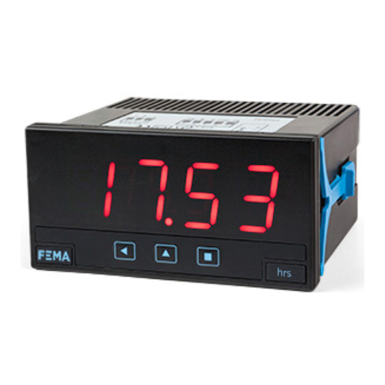
Series K . K40-CR
Chronometer, time counter
PANEL METERS
Chronometer and time counter, with 20 mm digit height. Configurable with up and down counting
modes. Independent controls for start, stop and reset. Display modes in decimal format and sexagesi-
mal (clock) format. Standard 96 x 48 mm size (1/8 DIN). Reading with 4 digit display. Fast access to
alarm setpoints, special modes for counting exceeded time and totalized counting times, 'on power
up' function, configurable led brightness. Universal AC and DC power. Up to 3 optional modules for
output and control (relays, transistor, control SSR, analog outputs, Modbus RTU communications, RS-
485 ASCII, RS-232, ...)
3620r05
ELECTRONICS
FOR
PANEL METERS . SIGNAL CONVERTERS . LARGE DISPLAYS
Tel. (+34) 93.729.6004 info@fema.es
User's Manual
INDUSTRIAL
AUTOMATION
www.fema.es
Advertisement
Table of Contents

Subscribe to Our Youtube Channel
Related Manuals for Fema Electronica K40-CR


Summary of Contents for Fema Electronica K40-CR
- Page 1 ELECTRONICS INDUSTRIAL AUTOMATION PANEL METERS . SIGNAL CONVERTERS . LARGE DISPLAYS Series K . K40-CR Chronometer, time counter PANEL METERS Chronometer and time counter, with 20 mm digit height. Configurable with up and down counting modes. Independent controls for start, stop and reset. Display modes in decimal format and sexagesi- mal (clock) format.
-
Page 2: Panel Meter K40-Cr
FEMA ELECTRÓNICA . Series K . K40-CR 1. Panel meter K40-CR Chronometer and time counter, size 96 mm (1/8 DIN), with 20 mm digit height Panel meter 96 x 48 mm (1/8 DIN) and 4 digits with 20 mm digit Several options allow to configure the display flash in case of ‘stop’... -
Page 3: Table Of Contents
Index 1. Panel meter K40-CR ..... . 2 1.13 Full configuration menu ....14 1.1 How to order . -
Page 4: Included Functions
FEMA ELECTRÓNICA . Series K . K40-CR 1.2 Included functions 1.4 Front view Alarms Control led* Functions included Section Fast access yes, configurable 1.12.5 Preset yes, configurable 1.12.1 yes, configurable : front, Reset rear and/or linked to alarm activation Logo... -
Page 5: Control Connections
FEMA ELECTRÓNICA . Series K . K40-CR 1.7 Types of reset 1.6 Control connections The reset function can be activated from three independent and con- • Normal connections (‘con.a’) - controls for ‘start’, ‘stop’ and ‘re- figurable sources: set’ are independent. Activation by default is by falling edge (by short-circuit to the 0 Vdc terminal). -
Page 6: Technical Specifications
FEMA ELECTRÓNICA . Series K . K40-CR 1.8 Technical specifications Digits Mechanical number of digits mounting panel 7 segments led connections plug-in screw terminal color housing material ABS, polycarbonate (V0) digit height 20 mm weight <150 grams front size 96 x 48 mm (1/8 DIN) -
Page 7: How To Operate The Menus
FEMA ELECTRÓNICA . Series K . K40-CR 1.10 How to operate the menus The instrument has two menus accessible to the user : Example of operation inside the ‘configuration menu’. ‘Configuration menu’ (key SQ) (<) 1. The SQ (<) key enters into the ‘Fast access’... -
Page 8: Configuration Menu
FEMA ELECTRÓNICA . Series K . K40-CR 1.12 Configuration menu Press ‘SQ’ (<) for 1 second to access the ‘configuration menu’. 1.12.1 Initial set-up For a description on how to operate inside the menus see section 1.10 . For a full vision of the ‘configuration menu’ structure see To configure the initial set up of the instrument, select the viewing 1.13... - Page 9 FEMA ELECTRÓNICA . Series K . K40-CR 1.12 Configuration menu (cont.) • the ‘State’ (‘StAt’) parameter controls the state of the counter after power-up. Select ‘Strt’ to count after power-up or ‘StoP’ to remain stopped after power-up. Flash ‘Flash on stop’...
-
Page 10: Controls Configuration
FEMA ELECTRÓNICA . Series K . K40-CR 1.12 Configuration menu (cont.) • function ‘B.4 exceeded’ (‘Fn.b.4’) enables an internal counter for exceeded time, which can be made visible on display by activation of channel ‘B’ signal. To reset the exceeded counter, view the counter Function B.4... -
Page 11: Alarms
FEMA ELECTRÓNICA . Series K . K40-CR 1.12 Configuration menu (cont.) els, value ‘on_h’ activates the reset on high signal value, and value Trigger level (from ‘on_0’ activates reset on low signal. Front reset activates always by 0 to 31). Each state. -
Page 12: Fast Access
FEMA ELECTRÓNICA . Series K . K40-CR 1.12 Configuration menu (cont.) • at ‘Activation delay’ (‘dEL.0’) configure the delay to apply before alarm activation. The activation delay starts counting when the set- point value is passed. Value from 0.0 to 99.9 seconds. -
Page 13: Super Fast Access
FEMA ELECTRÓNICA . Series K . K40-CR 1.12 Configuration menu (cont.) 1.12.6 Super fast access If only a single function is selected for the ‘fast access’ menu, press- ing the the ‘UP’ (5) key will shortly display the function name and then automatically jump to the function value. -
Page 14: Full Configuration Menu
FEMA ELECTRÓNICA . Series K . K40-CR 1.13 Full configuration menu Press ‘SQ’ (<) for 1 second to access the ‘Configuration menu’. See 1.12 section for a description of each menu entry. Function on channel ‘B’ 0.00 to 99.59 Function View format 0.00 to 99.59... - Page 15 FEMA ELECTRÓNICA . Series K . K40-CR 1.13 Full configuration menu (cont.) ‘Start’ Alarms Disabled Alarm 1 Alarm mode Normal Function B.5 ‘hold’ Repeat Type of alarm Function B.6 ‘Max / min’ Setpoint Activation delay No pull Pulls for Controls Pull up ‘Start’ and ‘Stop’...
-
Page 16: Factory Configuration
FEMA ELECTRÓNICA . Series K . K40-CR 1.13 Full configuration menu (cont.) Configuration menu for the module installed at Opt.1 Key UP Tools Setpoint 1 Option (‘Fast access’) Configuration menu for the module installed at Opt.2 Setpoint 2 Option Configuration menu for the module installed at Opt.3 ... -
Page 17: Application Example 1
FEMA ELECTRÓNICA . Series K . K40-CR 1.15 Application example 1 1.16 Application example 2 In an industrial process of electrolytic bath, the wetted parts need An industrial process has an oven to dry different elements. The dry- to be removed from the bath and replaced with new parts every 20 ing time of each element is variable, and the operator requires that minutes. -
Page 18: To Access The Instrument
FEMA ELECTRÓNICA . Series K . K40-CR 1.17 To access the instrument To open the housing, use a flat screwdriver to free the fixation clips, if possible, in the following order : D, C, B and A. Remove the front cover. -
Page 19: Precautions On Installation
FEMA ELECTRÓNICA . Series K . K40-CR 1.19 Precautions on installation 1.21 CE declaration of conformity Manufacturer FEMA ELECTRÓNICA, S.A. Risk of electrical shock. Instrument terminals can be connected Altimira 14 - Pol. Ind. Santiga to dangerous voltage. E08210 - Barberà del Vallès BARCELONA - SPAIN Instrument protected with double isolation. -
Page 20: Output And Control Modules
FEMA ELECTRÓNICA . Series K . K40-CR 2. Output and control modules 2.1 Module R1 2.2 Module T1 The R1 module provides 1 relay output to to install at digital panel The T1 module provides 1 transistor output to install at digital panel meters from Series K, up to a maximum of 3 relays in a single meter. -
Page 21: Module Ssr
FEMA ELECTRÓNICA . Series K . K40-CR 2.3 Module SSR 2.4 Module AO The SSR module provides 1 output to control SSR relays, to install at The AO module provides 1 analog output with 4/20 mA or 0/10 Vdc digital panel meters from Series K, up to a maximum of 3 SSR con- configurable output range. -
Page 22: Module Rtu
FEMA ELECTRÓNICA . Series K . K40-CR 2.6 Module RTU 2.5 Module S4 The S4 module provides a RS-485 communications module for Series The RTU module provides a Modbus RTU communications module for Series M of panel meters. The RTU module implements function M of panel meters. -
Page 23: Module S2
FEMA ELECTRÓNICA . Series K . K40-CR 2.7 Module S2 2.8 Modules R2, R4, R6 The S2 module provides a RS-232 communications module for Series The R2, R4 and R6 modules provide 2, 4 and 6 relay outputs for Series M of panel meters. -
Page 24: Other Options
FEMA ELECTRÓNICA . Series K . K40-CR 3. Other options 3.1 Option NBT Instruments without front key- pad. To configure the instrument, remove the meter from the panel and remove the front filter. Inter- nal press buttons for configuration are accessible. Optionally, request... -
Page 25: Accessories
FEMA ELECTRÓNICA . Series K . K40-CR 4. Accessories 4.1 THM benchtop housing 4.4 WME housing Benchtop housing for Series M Wall mount housing. Together and Series K of panel meters. with the KIP protector, offer a Handle with three selectable posi- full IP65 protection. - Page 26 FEMA ELECTRÓNICA . Series K . K40-CR Notes...
- Page 27 FEMA ELECTRÓNICA . Series K . K40-CR Notes...
Need help?
Do you have a question about the K40-CR and is the answer not in the manual?
Questions and answers