
Related Manuals for ETEKCITY MSR-R500


Summary of Contents for ETEKCITY MSR-R500
- Page 1 Digital Multimeter Model No.: MSR-R500 Questions or Concerns? (855) 686-3835 • support@etekcity.com...
- Page 2 Safe and Proper Usage Thank you for purchasing the Etekcity® MSR-R500 Digital Multimeter. Measure DC and AC voltage, current, diode and audible continuity, and resistance with the convenience of one single tool with built-in overload protection. WARNING: TO AVOID THE RISK OF ELECTRIC...
- Page 3 equipment out of humidity or moist environments. • DO NOT use the meter if it is damaged or the case (or part of the case) is removed. Look for cracks or missing plastic. Check the insulation around the connectors before use. •...
- Page 4 voltages are greater than 25VAC rms or 35VDC. These voltages are considered to be a shock hazard. • DO NOT operate the meter with the battery cover removed or the case open. • DO NOT remove the cover or open the case of the meter without first removing it from the main power source.
-
Page 5: Button Functions
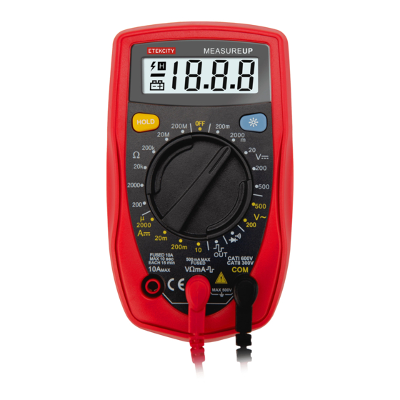
Meter Diagram 1. LCD Display 2. HOLD Button 3. Backlight Button 4. Rotary Switch 5. COM Terminal 6. 10A Terminal 7. Other Terminals Figure 1 Button Functions Button Operation • Press once to lock measurement HOLD results (An ‘H’ symbol will appear on the display) •... -
Page 6: General Specifications
General Specifications 500V rms Maximum Voltage (Including transient overvoltage) Between any Terminals & Grounding 500mA, 250V fast type, Fused Protection for φ5x20mm V mA Input Terminal 10A, 250V fast type, 10A Terminal φ5x20mm Manual Ranging Range 1999 Maximum Display Updates 2 ~ 3 times/second Measurement Speed Operating: 0°C ~ 40°C (32°F ~ Temperature... - Page 7 Battery Type: 1 x 9V Battery NEDA 1604 / 6F22 / 006P Overload Display: Dimensions: 130 x 73.5 x 35mm Weight: ~156g DC Voltage Accuracy Overload Range Resolution Protection 250V DC 200mV 100µV or AC ± (0.5% +2) 2000mV 10mV 500V DC or AC 200V...
- Page 8 DC Current Overload Accuracy Range Resolution Protection 2000µA 1µA 500mA, ± (1% +2) 250V fast 20mA 10µA type fuse: ± (1.2% +2) 200mA 100µA 5x20mm 10A/250V fast type ± (2%+5) 10mA φ 5x20mm At 10A Range: for continuous measurement ≤ 10 seconds and interval not less than 15 minutes Resistance Overload...
- Page 9 Diodes and Continuity Measurement Overload Range Resolution Remark Protection Display approximate forward voltage 250V DC or AC drop: 0.5v ~ 0.8v Buzzer beeps at < 70 Square Wave Output Range Illustration Approx. output 50Hz square wave signal. As a simple signal source with 47K resistance output.
-
Page 10: Measurement Operation
Measurement Operation DC Voltage Measurement Figure 2 DC Voltage Ranges: 200mV, 2000mV, 20V, 200V, 500V Input Impedance: 10M 1. Plug the red test lead into the V mA terminal, then plug the black test lead into the COM terminal. 2. Set the rotary switch to the appropriate measurement in V range. - Page 11 AC Voltage Measurement (See Figure 2) 200V, 500V AC Voltage Ranges: Input Impedance: 1. Plug the red test lead into the V mA terminal, then plug the black test lead into the COM terminal. 2. Set the rotary switch to the appropriate measurement in V~ range.
- Page 12 DC Current Measurement WARNING Never attempt an in-circuit current measurement where the voltage between the terminals and ground is greater than 60V. If the fuse burns out during measurement, this may cause harm to the user and/or damage to the device. Use proper terminals, functions, and range for measurement.
- Page 13 7. When measurement is completed, disconnect the test leads from the object of measurement. NOTE If the value of voltage is unknown, use the maximum measurement position (10A) and reduce the range until proper readings are obtained. Resistance Measurement Figure 4 Resistance Ranges: 200 , 2000 , 20k , 200k , 20M , 200M...
- Page 14 the input terminals beforehand and record the reading obtained (reading X). This is the additional resistance from the test lead. Then use the equation: Measured resistance value (Y) - (X) = resistance result • For high-resistance measurements (>1M ), it may take a few seconds for the reading result to stabilize.
- Page 15 1. Plug the red test lead into the V mA terminal, then plug the black test lead into the COM terminal. 2. Set the rotary switch to the setting. 3. For forward voltage drop readings on any semiconductor component, place the red test lead on the component’s anode and place the black test lead on the component’s cathode.
- Page 16 Square Wave Output WARNING To avoid damage to the meter and/or the object of measurement, do not allow output terminals (red test lead) to surpass 10V. 1. Plug the red test lead into the V mA terminal, then plug the black test lead into the COM terminal. 2.
-
Page 17: Maintenance
Maintenance WARNING • To avoid false readings, possible electrical shock and/or personal injury, replace the battery as soon as the low battery indicator appears on the display. • To avoid electrical shock, arc blast, personal injury, and/or damage to the meter, use the specified fused ONLY in accordance with the following procedure. -
Page 18: Warranty Information
2 years from the date of original purchase. Etekcity agrees, at our option during the warranty period, to repair any defect in material or workmanship or furnish an equal product in exchange without charge, subject to verification of the defect or malfunction and proof of the date of purchase. - Page 19 This warranty does not extend to products purchased from unauthorized sellers. Etekcity’s warranty extends only to products purchased from authorized sellers that are subject to Etekcity’s quality controls and have agreed to follow its quality controls. All implied warranties are limited to the period of this limited warranty.
-
Page 20: Customer Support
Customer Support If you encounter any issues or have any questions regarding your new product, please contact our helpful Customer Support Team. Your satisfaction is our goal! Etekcity Corporation Support Hours 1202 N Miller St., Suite A Mon - Fri,...
Need help?
Do you have a question about the MSR-R500 and is the answer not in the manual?
Questions and answers