
Subscribe to Our Youtube Channel
Related Manuals for ETEKCITY MSR-A1000


Summary of Contents for ETEKCITY MSR-A1000
- Page 1 Digital Multimeter Model No.: MSR-A1000 Questions or Concerns? support@etekcity.com • (855) 686-3835...
- Page 2 Thank you for purchasing the MSR-A1000 Digital Multimeter by Etekcity. If you have any questions or concerns, please reach out to our helpful Customer Support Team at support@etekcity.com. We hope you enjoy your new multimeter! BECOME AN ETEKCITIZEN Get exclusive deals, giveaways, and product registration.
-
Page 3: Table Of Contents
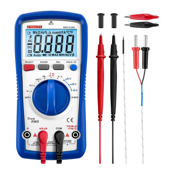
Table of Contents Package Contents Package Contents 1 x Digital Multimeter Safety Information 2 x 1.5V AA Batteries (Pre-Installed) • Electrical Symbols 2 x Test Leads Multimeter Features 1 x Temperature Probe • Display Symbols 2 x Alligator Clip Cables •... -
Page 4: Safety Information
Safety Information WARNING The following safety certification standards • To reduce the risk of fire, electrical shock, apply to this multimeter: or other serious injury, please read and follow all instructions and warnings in this • CE certifications manual. • EN 61010-1:2010 and EN 61010-2-030:2010 •... -
Page 5: Electrical Symbols
Electrical Symbols WARNING • To avoid electric shock, be extremely High Voltage Hazard cautious when the measured voltage is higher than DC 60V or AC 30Vrms. • To avoid damaging the multimeter, Double Insulation always turn the rotary dial to the correct position when using. -
Page 6: Multimeter Features
Multimeter Features The MSR-A1000 is a multifunctional multimeter with a large LCD screen, true RMS, and both auto and manual range. This multimeter is designed with a new intelligent ADC chip, overvoltage and overcurrent alarms, lightning protection (6kV), and high voltage protection. -
Page 7: Display Symbols
Display Symbols Symbol Description Symbol Description Auto power-off Megaohm, 1 x 10 or 1,000,000 ohms High voltage warning Volts (voltage) Data hold is active Millivolt, 1 x 10 or 0.001 of a volt Indicates a negative reading Amperes or amps (current) AC measurement indicator Milliamp, 1 x 10 or 0.001 of an... -
Page 8: Button Functions
Button Functions Button Description Press to switch between resistance/diode/continuity/ capacitance, °C/°F SELECT temperature, and AC/DC current. Press to switch to manual range at ACV, DCV, mV, RANGE resistance, uA, mA and A positions. Press to clear the base value at ACV, DCV, mV, resistance/ capacitance, uA, mA and A positions. -
Page 9: Operation
Operation General Use • Inspect the test leads for damaged insulation • Remember to replace the batteries as soon or exposed metal parts. Check the leads for as the low battery indicator appears continuity. Replace damaged test leads if (see Replacing the Batteries, page 19). The necessary. -
Page 10: Dc/Ac Voltage Measurement
AC Voltage, DC Voltage, and DC Note: • If the range of the measured voltage is unknown Millivoltage Measurement before measuring, select the maximum range and then gradually reduce the measuring range WARNING until the multimeter shows an accurate reading. •... -
Page 11: Resistance Measurement
Resistance Measurement • When measuring low resistance, the resistance of the test leads may affect the test result, causing a 0.1Ω–0.2Ω measurement error. To WARNING get an accurate measurement, first test the resistance of the test leads by connecting them Before measuring, switch off the power to each other, and subtract this value from the final measurement result. -
Page 12: Continuity Measurement
Continuity Measurement WARNING Before measuring, switch off the power supply of the circuit, and fully discharge all capacitors. Turn the rotary dial to the continuity ( position. [Figure 4.1] Insert the black test lead into the COM terminal, and the red test lead into the Figure 4.1... -
Page 13: Diode Measurement
Diode Measurement Note: WARNING • The display will show “ ” if the test leads are incorrectly connected, if the polarity is Before measuring, switch off the power reversed, or if the diode is open. supply of the circuit, and fully discharge •... -
Page 14: Capacitance Measurement
Capacitance Measurement • The display will show “ ” if the measured WARNING capacitor is short-circuited or the capacitance exceeds the maximum range. Before measuring, switch off the power • When measuring large volume capacitors, it is supply of the circuit, and fully discharge normal to wait for several seconds to obtain a all capacitors. -
Page 15: Dc/Ac Current Measurement
DC/AC Current Measurement Note: WARNING • If the range of the measured current is unknown before measuring, select the maximum range • Before measuring, switch off the and then gradually reduce the measuring range power supply of the circuit, and until the multimeter shows an accurate reading. -
Page 16: Temperature Measurement
Temperature Measurement Turn the rotary dial to the temperature Connect the test leads in parallel to the (°F°C) position. Press SELECT to choose signal source. Hold them in place until the Fahrenheit or Celsius units. [Figure 8.1] reading on the display stabilizes. Use the type K thermocouple temperature Note: probe. -
Page 17: Non-Contact Ac Electric Field Sensing
Non-Contact AC Electric Field Sensing This test detects whether there is an AC voltage or electromagnetic field in an area, without touching the area or object being measured. Turn the rotary dial to the NCV position. [Figure 10.1] Place the front end of the multimeter near the object being measured. -
Page 18: Other Functions
Other Functions • The multimeter will be ready to take • If AC/DC current is over 10A, the measurements 2 seconds after startup. multimeter will beep continuously to warn that the range is over its limit. • If the multimeter is not used for 15 minutes, it will automatically turn off to save power. -
Page 19: Maintenance
Maintenance General Maintenance Remove the old batteries. Install 2 new 1.5V AA batteries into the compartment under the correct polarity. [Figure 11.1] • Clean the multimeter with a damp cloth and mild detergent. Do not use abrasives or Replace and secure the battery solvents. -
Page 20: Replacing The Fuses
Replacing the Fuses Note: The fuses may burn out because of overcurrent or testing voltage improperly, and the multimeter will not work correctly. Replace any burnt-out fuses. Disconnect the test leads and turn the rotary dial to OFF. Remove the protective jacket from the multimeter. -
Page 21: Technical Index
Technical Index Specifications Display Measurements 6000 counts with fast ADC (4 times/sec), true RMS Response time <12s when capacitance ≤60mF Capacitance Measurement Max voltage between input terminal and 1000Vrms ground Fuse 10A H 1000V fast-acting fuse Φ6×32mm A Terminal Fuse 600mA H 1000V fast-acting fuse Φ6×32mm mA/μA Terminal Range Auto... - Page 22 Technical Index (cont.) Specifications Dimensions 7.4 x 3.5 x 2.2 in (187 x 88 x 56 mm) Weight About 14 oz (~400 g) including batteries RF field (1V/m): overall accuracy = specified accuracy + 5% of range RF field (>1V/m): no specified calculation ±(a% of reading + b digits) Accuracy Format Ambient temperature for high accuracy...
- Page 23 i. AC Voltage Measurement ii. DC Voltage Measurement Range Resolution Accuracy Range Resolution Accuracy 0.001V 60mV 0.01mV ±(1.0%+3) ±(0.7%+5) 0.01V 600mV 0.1mV 600V 0.1V ±(0.8%+5) ±(0.5%+2) 750V 0.01V 600V 0.1V • Input impedance is about 10MΩ. • Frequency response: 40 – 400Hz, sine ±(0.7%+5) 1000V wave rms (average response).
- Page 24 iii. Resistance Measurement iv. DC Current Measurement Range Resolution Accuracy Range Resolution Accuracy ±(0.8%+5) 600Ω 0.1Ω 60μA 0.01μA 6kΩ 0.001kΩ 600μA 0.1μA ±(0.8%+8) ±(0.8%+3) 60kΩ 0.01kΩ 6000μA 1μA 600kΩ 0.1kΩ 60mA 0.01mA ±(3.0%+10) ±(1.2%+5) 60MΩ 0.01MΩ 600mA 0.1mA 0.001A • Measurement result = reading of resistance ±(2.0%+5) after subtracting reading of shorted test leads 0.01A...
- Page 25 v. AC Current Measurement vi. Frequency Measurement Range Resolution Accuracy Range Resolution Accuracy 60μA 0.01μA 9.999Hz– 0.001Hz– ±(0.1%+5) 9.999MHz 0.001MHz 600μA 0.1μA ±(1.0%+12) • Overload protection: 1000Vrms (DC/AC) 6000μA 1μA • Input amplitude: 60mA 0.01mA ○ ≤100kHz: 100mVrms ≤ input amplitude ≤ 30Vrms 600mA 0.1mA...
- Page 26 viii. Capacitance Measurement vii. Continuity & Diode Measurement Range Resolution Accuracy Range Resolution Accuracy REL mode: If the measured 0.001nF resistance is greater ±(4%+10) than 50Ω, the 60nF 0.01nF multimeter will read the circuit as open, 600nF 0.1nF and the multimeter will not beep.
- Page 27 ix. Temperature Measurement Range Resolution Accuracy ±4°C -40°C–40°C ±(1.0%+4) °C -40°C–1000°C >40°C–500°C 1°C ±(2.0%+4) >500°C–1000°C ±5°C -40°F–104°F ±(1.5%+5) °F -40°F–1832°F >104°F–932°F 1°F ±(2.5%+5) >932°F–1832°F • The included type K (NiCr–NiSi) thermocouple can only be used for temperature lower than 482°F (250°C). Use a different thermocouple for higher temperatures. •...
-
Page 28: Warranty Information
TERMS & POLICY • Damage in return transit. • Unsupervised use by children under 18 Etekcity warrants all products to be of the highest years of age. quality in material, craftsmanship, and service, effective from the date of purchase to the end of Etekcity and its subsidiaries assume no liability the warranty period. - Page 29 Defective Products & Returns Should your product prove defective within the specified warranty period, please contact Customer Support via support@etekcity.com with your invoice and order number. Do not dispose of your product before contacting us. Once our Customer Support Team has approved your request, please return the...
-
Page 30: Customer Support
If you encounter any issues or have any questions regarding your new product, please contact our helpful Customer Support Team. Your satisfaction is our goal! Customer Support Support Hours Etekcity Corporation Mon–Fri, 9:00 am–5:00 pm PST/PDT 1202 N. Miller St., Suite A Anaheim, CA 92806 Toll Free: (855) 686-3835 Email: support@etekcity.com... - Page 31 Connect with us @Etekcity...
- Page 32 Building on better living. v01.00...
Need help?
Do you have a question about the MSR-A1000 and is the answer not in the manual?
Questions and answers