Etekcity MSR-C600 Digital Clamp Multimeter Manual
- Operating manual (17 pages)
Advertisement
Overview
This Operating Manual covers information on safety and cautions. Please read the relevant information carefully and observe all the Warnings and Notes strictly.

To avoid electric shock or personal injury, read the "Safety Information" and carefully before using the Meter.
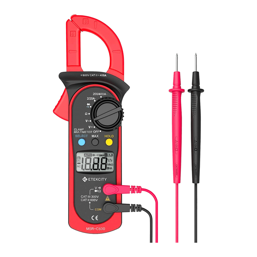
MSR-C600 is 2000-count stable, safe and reliable digital clamp multimeter. It is designed with large-scale integrated circuits and A/D converter as the core as well as the overload protection and novel structure, which make it a superb tool for electricians. The Meter can measure AC/DC voltage, AC current, resistance, diode, continuity and so on.
Unpacking Inspection
Open the package case and take out the Meter. Check the following items carefully for any missing or damaged part:
| Item | Description | Qty |
| 1 | Digital Clamp Multimeter | 1 pc |
| 2 | Carrying Pouch | 1 pc |
| 3 | User Manual | 1 pc |
Safety Information
This Meter complies with the standard IEC61010: Pollution Degree 2, Overvoltage Category (CAT. II 600V, CAT. III 300V) and Double Insulation.
CAT. II: Local level, appliance, PORTABLE EQUIPMENT etc., with smaller transient overvoltages than CAT. III.
CAT. III: Distribution level, fixed installation, with smaller transient overvoltages than CAT. IV
Use the Meter only as specified in this operating manual, otherwise the protection provided by the Meter may be impaired. In this manual, a Warning identifies conditions and actions that pose hazards to the user, or may damage the Meter or the equipment under test.
A Note identifies the information that user should pay attention to.
To avoid possible electric shock or personal injury, and to avoid possible damage to the Meter or to the equipment under test, adhere to the following rules:
Before using the Meter inspect the case. Do not use the Meter if itis damaged or the
case (or part of the case) is removed. Look for cracks or missing plastic. Pay
attention to the insulation around the connectors.
- Inspect the test leads for damaged insulation or exposed metal. Check the test leads for continuity. Replace damaged test leads with identical model number or electrical specifications before using the Meter.
- Do not apply more than the rated voltage, as marked on the Meter, between the terminals or between any terminal and grounding. Ifthe value to be measured is unknown, use the maximum range and reduce the range step by step until a satisfactory reading is obtained.
- When measurement has been completed, disconnect test leads from the circuits under test, remove the testing leads away from the input terminals of the Meter and turn the Meter power off.
- The rotary switch should be placed in the right position and no any changeover of range shall be made during measurement to prevent damage of the Meter.
- To avoid electric shock, do not carry out the measurement when the Meter's back case and battery compartment are not closed.
- Do not input higher than 600V between the Meter's terminals and the grounding to avoid electric shock and damages to the Meter.
- When the Meter working at an effective voltage over 60V in DC or 30V rms in AC, special care should be taken for there is danger of electric shock.
- Use the proper terminals, function, and range for your measurements.
- Do not use or store the Meter in an environment of high temperature, humidity, explosive, inflammable and strong magnetic field. The performance of the Meter may deteriorate after dampened.
- When using the test leads, keep your fingers behind the finger guards.
- Disconnect circuit power and discharge all high-voltage capacitors before teresistance, continuity and diode.
- Replace the battery as soon as the battery indicator E2appears. With a low battery, the Meter might produce false readings that can lead to electric shock and personal injury.
- When servicing the Meter, use the replacement parts with the same model or identical electrical specifications.
- To avoid any damage to the meter or any accident, do not alter the internal circuit of the Meter randomly.
- Soft cloth and mild detergent should be used to clean the surface of the Meter when servicing.
- No abrasive and solvent should be used to prevent the surface of the Meter from corrosion, damage and accident.
- The Meter is suitable for indoor use.
- Turn the Meter off when it is not in use and take out the battery when not using for a long time.
- Constantly check the battery as it may leak when jt has been used for some time, replace the battery as soon as leaking appears. A leaking battery will damage the Meter.
International Electrical Symbols
 | AC (Alternating Current). |
 | DC (Direct Current). |
 | AC or DC. |
 | Grounding. |
 | Double Insulated. |
 | Deficiency of Built-In Battery |
 | Continuity Test. |
 | Diode. |
 | Fuse. |
 | Refer to the Operating Manual. |
 | Danger of High Voltage |
 | Conforms to Standards of European Union. |
The Meter Structure

- Input Terminals
- LCD Display
- Functional Buttons
- Rotary Switch
- Trigger: Push/release it to open/close the clamp jaw.
- Hand Guards: to protect user's hand from touching the dangerous area.
- Transformer Jaws: designed to pick up the AC current flowing through the conductor. It could transfer current to voltage.
Rotary Switch
Below table indicated for information about the rotary switch positions.
| Rotary switch positions | Function |
| OFF | Power is turned off. |
 | DC voltage measurement |
 | AC voltage measurement |
 | Resistance measurement |
 | Continuity/diode test |
 2/20A 2/20A | AC current measurement from 0.001A to 400A |
| 200/400A |
Functional Buttons
Below table indicated for information about the functional button operations.
HOLD  | Press HOLD to enter and exit the Hold mode in any mode, the Meter beeps. |
| MAX | Press MAX to start recording and updating of maximum values. |
| SELECT | Press SELECT button to switch between  and and  . . |
Functional Buttons
Not every functional buttons can be used on every rotary switch positions.

Display Symbols
(See Figure 2)
Not every functional buttons can be used on every rotary switch positions.

| No. | Symbol | Description |
| 1 | AC | Indicator for AC voltage or current |
| 2 | DC | Indicator for DC voltage |
| 3 |  | The battery is low. To avoid false readings, which could lead to possible electric shock or personal injury, replace the battery as soon as the battery indicator appears. |
| 4 |  | The Meter is in the auto range mode in which the Meter automatically selects the range with the best resolution. |
| 5 |  | Test of diode. |
| 6 |  | The continuity buzzer is on. |
| 7 | MAX | Maximum reading displayed |
| 8 |  | Date hold is active. |
| 9 | Ω,kΩ,MΩ | Ω: Ohm. The unit of resistance. kΩ: kilohm.1 x 10 3 or 1000 ohms. MΩ: Megaohm. 1 x 10 6 or 1,000,000 ohms. |
| 10 | A | Amperes (amps). The unit of current. |
| 11 | mV, V | Volts. The unit of voltage.mV: Millivolt. 1x10 -3 or 0.001 volts |
| 12 |  | Indicates negative reading |
| 13 | OL | The input value is too large for the selected range. |
Measurement Operation
DC Voltage measurement

To avoid harms to you or damages to the Meter from eletric shock, do not attempt to measure voltages higher than 600V AC/DC, although readings may be obtained.
The DC Voltage ranges are: 200.0mV, 2.000V, 20.00V, 200.0V and 600V. To measure DC voltage, connect the Meter as follows:
- Insert the red test lead into the
![]() terminal and the black test lead into the COM terminal.
terminal and the black test lead into the COM terminal. - Set the rotary switch to
![]() .
. - Connect the test leads across with the object being measured. The measured value shows on the display.

 .
.Note
- In each range, the Meter has an input impedance of 10MQ. This loading effect can cause measurement errors in high impedance circuits. If the circuit impedance is less than or equal to 10kQ, the error is negligible (0.1 or less).
- When DC voltage measurement has been completed, disconnect the connection between the testing leads and the circuit under test and remove testing leads from the input terminals.
Measuring AC Voltage
(See Figure 4)

To avoid harms to you or damages to the Meter from eletric shock, do not attempt to measure voltages higher than 600V AC/DC, although readings may be obtained.
The AC Voltage ranges are: 2.000V, 20.00V, 200.0V and 600V
To measure AC voltage, connect the Meter as follows:
- Insert the red test lead into the
![]() terminal and the black test lead into the COM terminal.
terminal and the black test lead into the COM terminal. - Set the rotary switch to
![]()
- Connect the test leads across with the object being measured. The measured value shows on the display.
 terminal and the black test lead into the COM terminal.
Note
- In each range, the Meter has an input impedance of 10M. This loading effect can cause measurement errors in high impedance circuits. If the circuit impedance is less than or equal to 10kQ, the error is negligible (0.1 or less).
- When AC voltage measurement has been completed, disconnect the connection between the testing leads and the circuit under test and remove testing leads from the input terminals.
Measuring Resistance
(See Figure 5)

To avoid harms to you, donot attempt to input voltages higher than 60V DC or 30V rms AC.
To avoid damages to the Meter or to the devices under test, disconnect circuit power and discharge all the high-voltage capacitors before measuring resistance.
The resistance ranges are:
200.09, 2.000kQ, 20.00k2,200kQ,2.000MQ and 20.00MQ.
To measure resistance, connect the Meter as follows:
- Insert the red test lead into the
![]() terminal and the black test lead into the COM terminal.
terminal and the black test lead into the COM terminal. - Set the rotary switch to
![]() .
. - Connect the test leads across with the object being measured.
The measured value shows on the display.
 .
.Note:
The test leads can add 0.12 to 0.32 of error to resistance measurement.
- For high-resistance measurement (>1MQ), it is normal taking several seconds to obtain a stable reading.
- If Q reading with shorted test leads is not<0.5Q, check for loose test leads, wrong function selected, or enabled data hold function.
- The LCD displays OL indicating open-circuit or the tested resistor value is higher than the maximum range of the Meter
- Resistance measurement is default to auto range mode.
- Measuring the tested object that is already removed from the in-line circuit can the in-line circuit can help to obtain a more accurate reading.
- When resistance measurement has been completed, disconnect the connection between the testing leads and the circuit under test and remove testing leads from the input terminals.
Testing Diodes
(See Figure 6)

To avoid damages to the Meter or to the devices under test, disconnect circuit power and discharge all the high-voltage capacitors before testing diodes.
Use the diode test to check diodes, transistors, and other semiconductor devices. The diode test sends a current through the semicondutor junction, then measure the voltage drop across the junction. A good silicon junction drops between 0.5V and 0.8V.
To test the diode out of a circuit, connect the Meter as follows:
- Insert the red test lead into the
![]() terminal and the black test lead into the COM terminal.
terminal and the black test lead into the COM terminal. - Set the rotary switch to
![]()
- For forward voltage drop readings on any semiconductor component, place the red test lead on the component's anode and the black test lead on the component's cathode.

Note
- In a circuit, a good diode should still produce a forward voltage drop reading of 0.5V to 0.8; however, the reverse voltage drop reading can vary depending on the resistance of other pathways between the probe tips.
- Connect the test leads to the proper terminals as said above to avoid error display.
- The LCD will display OL indicating either open circuit or wrong polarity connection.
- The unit of diode is volt (V), displaying the forward voltage drop readings.
- Measuring the tested object that is already removed from the in-line circuit can help to obtain a more accurate reading.
- When diode testing has been completed, disconnect the connection between the testing leads and the circuit under test and remove testing leads from the input terminals.
Testing for Continuty
(See Figure 7)

To avoid damages to the Meter or to the devices under test, disconnect circuit
power and discharge all the high-voltage capacitors before measuring continuity.
To test for continuity, connect the Meter as follows:
- Insert the red test lead into the «VO terminal and the black test lead into the COM terminal.
- Set the rotary switch to =)-+ and press SELECT button to select +) measurement mode.
- The buzzer sounds if the resistance of a circuit under test is less than 50Q.
- The buzzer may or may not sounds if the resistance of a circuit under test is between 502to 1202.
- The buzzer does not sound if the resistance of a circuit under test is higher than 1200.
Note
- The buzzer beeps 5 times continuously on around 1 minute before entering the sleep mode. When it is just before entering the sleep mode, it will have one long beep to warn you.
- The LCD displays OL indicating the circuit being tested is open.
- When continuity testing has been completed, disconnect the connection between the testing leads and the circuit under test and remove testing leads from the input terminals.
Measuring AC Current
(See Figure 8)

To avoid electric shock, never measure current while the test leads are inserted into the input terminals and disconnect test leads and tested circuit connection.
Never attempt an in-circuit current measuremnet where the open-circuit voltage between the circuit and the ground is greater than 600V
Use proper function and range for the measurement.
The measuremnet ranges of current are: 2.000A, 20.00A, 200.0A and 400A.
To measure current, do the following:
- Set the rotary switch to 2/20A~or 200/400 A~
- Press the trigger to open the transformer jaws.
- Center the conductor within the transformer jaw. then release the Meter slowly until the transformer jaw is completely closed, Make sure the conductor to be to be tested is placed at the center of the transformer jaw, otherwise it will casue deviation.
- The measured value shows on the display, it is a effective value of sine wave (mean value response)
Note:
- To obtain accurate reading, measure only one conductor at each time.
- When current measurement has been completed, disconnect the connection between the conductor under test and the jaw, and remove the conductor away from the transformer jaw of the Meter.
Sleep Mode
To preserve battery life, the Meter automatically turns off if you do not turn the rotary switch or press any button for around 15 minutes. The Meter can be activated by turning the rotary switch or pressing any button with the following conditions:
The Hold function will be cancelled if the Meter is activated by pressing the HOLD button. To disable the Sleep Mode function, press and hold HOLD button while turning on the Meter.
Specifications
General Specifications
- Maximum voltage including transient overvoltage between any terminals and grounding: 600V rms
- Display: Maximum display 1999
- Auto Polarity Display
- Overloading: Display OL or -OL
- Low Battery Indication: Display
![]()
- Measurement Speed _: Updates 3 times/second.
- Measuremnet Deviation: When the conductor being meaured is not placed in a correct position during AC current measurement, it will cause +1% reading deviation.
- Drop Test: 1 meter drop test passed.
- Max. Jaw Opening 28mm diameter.
- Tested Max. Current conductor size: 26mm diameter.
- Power 2pes of 1.5V battery (AAA)
- Battery Life: typically 150hours (alkaline battery)
- Sleep Mode (can be disabled)
- Dimensions (H x Wx L): 30mm x 76mm x 208mm.
- Weight: Approximate 260g (battery included)

Environmental Restrictions
- The Meter is suitable for indoor use.
- Altitude: Operating: 2000m Storage: 10000m
- Safety/Compliances_: IEC 61010 CAT.II GOOV, CATLIII 300V over voltage and double insulation.
- Temperature and Humidity: Operating: 0°C~30°C (<75% R.H);30°C~40°C &70%R.H); 40°C~50'C (<45%R.H); Storage: -20°C~+60'C (S75%R.H)
Accuracy Specifications
Accuracy: +(a% reading + b digits), guarantee for 1 year
Operating temperature: 23°C + SC
Relative humidity: <75%R.H
- AC Voltage: Auto Ranging
| Range | Resolution | Accuracy | Overload Protection |
| 2.000V | 1mV |  (1.2%+5) (1.2%+5) | 600V rms |
| 20.00V | 10mV | ||
| 200.0V | 100mV | ||
| 600V | 1V | (1.5%+5) |
Remarks:
- Input impedance: 10
![]() <100pF
<100pF - Display sinewave RMS{ AVG response)
- Frequency response: 40H2~1kH2.
- To adjust reading in accordance with effective value
- DC Voltage: Auto Ranging
| Range | Resolution | Accuracy | Overload Protection |
| 200.0mV | 0.1mV | (0.8%+3) | 600V rms |
| 2.000V | 1mV | (0.8%+1) | |
| 20.00V | 10mV | ||
| 200.0V | 100mV | ||
| 600V | 1V | (1%+3) |
Remarks: Input impedance: 10M
- Resistance: Auto Ranging
| Range | Resolution | Accuracy | Overload Protection |
| 200.0 | 100m | (1.2%+2) | 600Vp |
| 2.000k | 1 | (1%+2) | |
| 20.00k | 10 | ||
| 200.0k | 100 | ||
| 2.000M | 1k | (1.2%+2) | |
| 20.00M | 10k | (1.5%+2) |
Remarks: Input impedance: 10M.
- Continuity Test
| Range | Resolution | Accuracy | Overload Protection |
 | 100m | Around 50 the buzzer beeps 50 the buzzer beeps | 600Vp |
Remark:
- Open circuit voltage approximate 0.45V.
- The buzzer may or may not beeps when the resistan of a circuit under test is between 502 and 1200
The buzzer may not beep when the resistance of a circuit under test is greater than 1202.
- Diode Test
| Range | Resolution | Accuracy | Overload Protection |
 | 1mV | Display approximate forward voltage drop: 05V~0.8V | 600Vp |
Remarks: Open circuit voltage approximate 1.48V.
- AC Current: Auto Ranging
| Range | Resolution | Accuracy | Frequency Response | Overload Protection |
| 2.000A | 0.001A | <1A(4%+40) 1A(3%+30) 1A(3%+30) | 50Hz~60Hz | 400A rms |
| 20.00A | 0.01A | (3%+12)4A(2%+8) | 50Hz~60Hz | 400A rms |
| 200.0A | 0.1A | (1.5%+5) | ||
| 400A | 1A |
Remarks:
- Displays sinewave RMS (AVG response)
To adjust reading in accordance with RMS value
Maintenance
This section provides basic maintenance information including battery replacement instruction.
Do not attempt to repair or service your Meter unless you are qualified to do so and have the relevant calibration, performance test, and service information. To avoid electrical shock or damage to the Meter, do not get water inside the case.
- General Service
- Periodically wipe the case with a damp cloth and mild detergent. Do not use abrasives or solvents.
- To clean the terminals with cotton bar with detergent, as dirt or moisture in the terminals can affect readings.
- Turn the Meter power off when it is not in use.
- Take out the battery when it is not using for a long time.
- Do not use or store the Meter in a place of humidity, high temperature, explosive, inflammable and strong magnetic field.
- Replacing the Battery
(See Figure 9 )


To avoid false readings, which could lead to possible electric shock or personal injur y, replace the battery as soon as the battery indicator " " appears.
Make sure the transformer jaw and the tets leads are disconected from the circuit being tested before opening the case bottom.
To replace the battery:
- Turn the Meter off and remove all the connections from the input terminals
- Turn the Meter's case top down.
- Remove the screw from the battery compartment, and separate the battery compartment from the case bottom.
- Remove the old battery from the battery compartment.
- Replace the battery with 2pcs of new 1.5V (AAA) battery.
- Rejoin the case bottom and the battery compartment, and reinstall the screw.
Questions or Concerns?
support@etekcity.com
visit etekcity.com for more products

VideosEtekcity Multimeter (MSR-C600) - How To (video)
Documents / Resources
References
Download manual
Here you can download full pdf version of manual, it may contain additional safety instructions, warranty information, FCC rules, etc.
Advertisement


Need help?
Do you have a question about the MSR-C600 and is the answer not in the manual?
Questions and answers