
Subscribe to Our Youtube Channel
Related Manuals for ETEKCITY MSR-A2000


Summary of Contents for ETEKCITY MSR-A2000
- Page 1 Digital Multimeter Model: MSR-A2000 User Manual Questions or Concerns? support@etekcity.com • (855) 686-3835...
-
Page 2: Table Of Contents
QR code to see the extended digital manual. Specifications Features You can also type the following link into a web browser: Safety Information Safety Terms and Symbols www.etekcity.com/support/manual/model/msr-a2000 Multimeter Features & Diagram Rotary Switch Keypad Display Screen Measurement Units Input Terminals... -
Page 3: Package Contents
Package Contents Features 1 × Digital Multimeter • Auto-Off 1 × User Manual • Backlit LCD Display 1 × 9V 6F22 Battery (Pre-Installed) 2 × Test Leads • Overload Protection 1 × K-Type Thermocouple • True RMS • Auto & Manual Range Options •... -
Page 4: Safety Information
READ AND SAVE THESE INSTRUCTIONS Safety Information Before using, read all instructions. Only use the • Before use, verify the multimeter’s operation multimeter as directed, or the multimeter may by measuring a known voltage. be damaged, and you may be seriously injured. •... - Page 5 Safety Information (cont.) • Do not operate the multimeter with the • When measuring current, turn off the circuit cover, or portions of the cover, removed or power before connecting the multimeter loosened. in the circuit. Remember to place the multimeter in series with the circuit.
- Page 6 Safety Information (cont.) • • Do not use or store the multimeter in wet or Disconnect circuit power and discharge all high- voltage capacitors before testing resistance, humid environments, in very high temperatures, continuity, diodes, or capacitance. around explosive or flammable substances, or in areas with strong magnetic fields.
- Page 7 Safety Information (cont.) Measurement Category Safety Rating Measurement CAT II applies to measurements performed on circuits directly connected to the low-voltage installation. Examples The multimeter has a safety rating of 1000V, are measurements on energy-consuming CAT III and 600V, CAT IV. equipment such as TVs, PCs, portable tools, and other household circuits.
-
Page 8: Safety Terms And Symbols
Safety Terms and Symbols Safety Terms Safety Symbols Terms in this Manual. The following terms may Symbols on the Product. The following symbol appear in this manual: may appear on the product: Warning: Warning indicates the conditions or Direct current practices that could result in personal injury or Fuse (DC) -
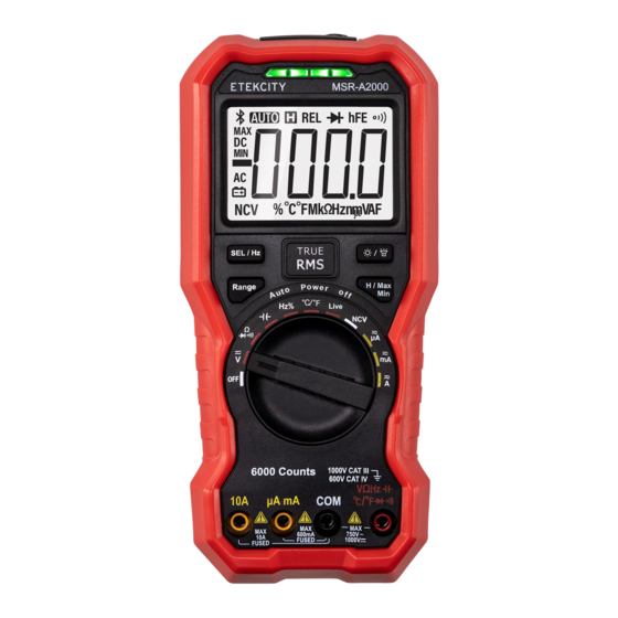
Page 9: Multimeter Features & Diagram
Multimeter Features Display Screen (see page 12) Keypad (see page 11) Rotary Switch (see page 10) Input Terminals (see page 15) LED Indicator Non-Contact Voltage Detector (NCV) (see page 24) Flashlight (see page 19) Accessories 9V 6F22 Battery (Pre-Installed) Test Leads K-Type Thermocouple... -
Page 10: Rotary Switch
Rotary Switch Position Description Details Position Description Details Single test lead living wire Power off Page 18 Page 24 detection DC or AC voltage measurement Page 20 Non-contact voltage detection Page 24 Resistance measurement Page 21 DC or AC current measurement, Page 26 Up to 6000 microamperes Continuity test... -
Page 11: Keypad
Keypad Description Details Select DC or AC. In ACV or ACA function, long press to display Hz —— Switch frequency / duty cycle when measuring frequency —— Switch °C/°F when measuring temperature —— Select Resistance/Continuity/Diode —— Auto/Manual range Page 19 Select Backlight or Flashlight Page 19 Short press to hold the reading... -
Page 12: Display Screen
Display Screen Symbol Description Details Auto range Page 33 Data hold enabled Page 28 Relative enabled —— Diode test selected Page 22 Transistor measurement ——... - Page 13 Display Screen (cont.) Position Description Details Position Description Details Continuity test selected Page 21 Battery is low Page 34 Measurement display (“OL” is short for overload. Maximum reading Page 28 —— Indicates the reading exceeds the display range) Page 31 Non-contact voltage detected Page 24 Minimum reading...
-
Page 14: Measurement Units
Measurement Units Sign Description Sign Description Measurement Type Degree Celsius Mega 1E+06 (1000000) Temperature Degree Fahrenheit kilo 1E+03 (1000) Voltage Voltage Ampere Current milli 1E–03 (0.001) Resistance Hertz Frequency micro 1E–06 (0.000001) Percent Duty cycle nano 1E–09 (0.000000001) Farad Capacitance... -
Page 15: Input Terminals
Input Terminals The terminal connections for the different measurement functions of the multimeter are described in the table below. Warning: Before starting any measurement, check the rotary switch position of the multimeter, and then connect the test leads to the correct terminals. Caution: To avoid damaging the multimeter, do not exceed the rated input limit. -
Page 16: Operation
Operation Getting Started Before first using your multimeter, follow these steps to check the instrument: Check for any damage caused by transportation. Check the Multimeter If the packaging carton or the foamed plastic If you find damage to the appearance of protection cushion have suffered serious damage, the multimeter, the multimeter does not do not throw them away until you finish testing the... - Page 17 Operation (cont.) Install the Batteries The multimeter is powered by a 9V (6F22) battery. Lift the tilt stand and loosen the screws with a suitable Phillips-head screwdriver and remove the battery cover. Warning: To avoid false readings, which Observe the battery polarity markings indicated could lead to possible electric shock or inside the battery compartment.
-
Page 18: Power Off
Operation (cont.) Adjust the Tilt Stand Sleep Mode Pull the tilt stand outward to The multimeter automatically enters sleep mode if the rotary switch is not moved or a key is not pressed its maximum reach (about for 30 minutes. 85°... - Page 19 Operation (cont.) LCD Backlight and Flashlight When the key is pressed briefly, the LCD • When auto-ranging mode is enabled, press backlight will be turned on. This is useful for testing to enter the manual-range mode. at night or in low-light conditions. After the backlight •...
-
Page 20: Taking Measurements
Taking Measurements Measuring AC or DC Voltage Warning: Do not measure any voltage of over Probe the test points and read the display. Press to enable and cycle through the 1000V DC or 750V AC RMS to avoid instrument damage or electric shock. manual ranges. -
Page 21: Resistance Measurement
Taking Measurements (cont.) Measuring Resistance Testing for Continuity Caution: To avoid possible damage to your Caution: To avoid possible damage to your multimeter or to the equipment undergoing multimeter or to the equipment undergoing testing, disconnect the circuit power and testing, disconnect the circuit power and discharge all high-voltage capacitors before discharge all high-voltage capacitors before... -
Page 22: Diode Test
Taking Measurements (cont.) Testing Diodes Measuring Capacitance Caution: To avoid possible damage to your Caution: To avoid possible damage to the multimeter or to the equipment undergoing multimeter or to the equipment undergoing testing, disconnect the circuit power and testing, disconnect circuit power and discharge discharge all high-voltage capacitors before all high-voltage capacitors before measuring testing diodes. -
Page 23: Frequency / Duty Cycle Measurement
Taking Measurements (cont.) Measuring Frequency Measuring Temperature Rotate the rotary switch to Rotate the rotary switch to Connect the red connection of the K-type Connect the black test lead to the terminal and the red test lead to the terminal. thermocouple to the terminal and the black connection to the... -
Page 24: Detection
Taking Measurements (cont.) Live Wire Detection Non-Contact Voltage Detection (NCV) Rotate the rotary switch to To detect the presence of AC voltage, place the Connect the red test lead to the terminal. top of the multimeter close to a voltage source. Measure the object undergoing testing with a When voltage is detected, the LED above the test lead. - Page 25 Taking Measurements (cont.) Non-Contact Voltage Detection (NCV) (cont.) Rotate the rotary switch to Test the NCV function on a known live circuit before use. Place the top of the multimeter very close to the voltage source as shown in Figure 2.1.
-
Page 26: Dc Or Ac Current Measurement, Up To 6000 Microamperes
Taking Measurements (cont.) Measuring DC or AC Current Warning: Never attempt an in-circuit current Connect the black test lead to the terminal. For currents below 600mA, connect measurement where the open-circuit potential to earth is greater than 250V. Doing so will cause the red test lead to the terminal. - Page 27 Taking Measurements (cont.) Select DC or AC measurement mode. Default Note: During AC current measurement, long is DC measurement mode, and will be press the key once to enter the frequency displayed. Press to switch into AC measurement mode, and long press it again to measurement mode, and will be displayed.
-
Page 28: Multimeter Features
Multimeter Features Data Hold Mode Buzzer Feature Press to freeze the display during • Press the function key, and the buzzer will emit a short beep. measurement, and will be shown on the display. • One minute before Auto Power-off, the buzzer will beep five times to warn the user that the Press again to exit this mode. - Page 29 Multimeter Features (cont.) Test Lead Insertion Detection Function • In the non-current function, when a test lead is inserted into input terminal, the multimeter will sound an alarm and display “LEAD” on the display. • In the current function, when the test lead is inserted into the input terminal, the multimeter will sound an alarm and display...
-
Page 30: Care & Maintenance
Care & Maintenance Warning: To avoid electrical shock or damage to the multimeter, ensure that the insides of the casing stay dry at all times. Cleaning To clean the multimeter exterior, follow these Turn the multimeter over and shake out the steps: dirt in the terminals. -
Page 31: Technical Specifications
Technical Specifications All these specifications apply to the multimeter Note: When measuring AC voltage/current or unless otherwise explained. capacitance, accuracy guarantee range is 5% to 100% of the range. Standard conditions: The environment temperature is 18°C to 28°C, and the relative humidity is less than 80%. - Page 32 Technical Specifications (cont.) Function Measurement Range Resolution Function 600.0μA/6000μA 0.1μA ±(1%+3dig) 60.00mA/600.0mA 0.01mA ±(1%+3dig) AC Current (A) 6.000A 0.001A ±(1.5%+3dig) 10.00A 0.01A ±(1.5%+3dig) 600.0Ω/6.000kΩ/60.00kΩ/600.0kΩ/6.000MΩ 0.1Ω ±(0.8%+2dig) Resistance (Ω) 60.00MΩ 0.01 MΩ ±(2%+3dig) 60.00nF/600.0nF/6.000μF/60.00μF 0.01nF ±(3%+3dig) Capacitance (F) 600.0μF/6.000mF/60.00mF 0.1μF ±(3%+5dig) 9.999Hz/99.99Hz/999.9Hz/9.999kHz/99.99kHz/ Frequency (Hz)
- Page 33 Technical Specifications (cont.) [1] When measuring current, for 8A to 10A, Note: When measuring resistance and the measuring duration should not be over capacitance, the influence of the resistance 2 minutes within a 10-minute time period, reactance of the pen itself on the measured value should be considered.
- Page 34 Technical Specifications (cont.) Characteristics Information Characteristics Information Battery 9V battery (6F22) Flashlight √ LCD Size 58.5 mm * 41 mm √ (The displayed when the Low Battery Indication Weight (without package) 0.32 kg battery is under the proper operation range.) Dimension 190 mm * 90 mm * 56 mm Data Hold...
- Page 35 Federal Communication Commission Interference Statement This device complies with Part 15 of the FCC Rules. Operation is subject to the following two conditions: This device may not cause harmful interference, and This device must accept any interference received, including interference that may cause undesired operation. NOTE: This equipment has been tested and found to comply with the limits for a Class B digital device, pursuant to Part 15 of the FCC Rules.
-
Page 36: Warranty Information
Etekcity Corporation (“Etekcity”) warrants this product to the original purchaser to be free from defects in material Etekcity will not be liable for indirect, incidental, or and workmanship, under normal use and conditions, for a consequential damages in connection with the use of the period of 2 years from the date of original purchase. - Page 37 Etekcity’s quality controls and have agreed to follow its quality controls. This warranty is made by: All implied warranties are limited to the period of this Etekcity Corporation limited warranty.
-
Page 38: Customer Support
Customer Support If you encounter any issues or have any questions about your new product, please contact our helpful Customer Support Team. Etekcity Corporation Support Hours 1202 N. Miller St., Suite A Anaheim, CA 92806 Monday—Friday 9:00 am —5:00 pm PST/PDT Email: support@etekcity.com... - Page 39 Notes...
- Page 40 Connect with us @Etekcity A2_21H24_US...
Need help?
Do you have a question about the MSR-A2000 and is the answer not in the manual?
Questions and answers
What are The 2 Replacement fuses
wHAT IS THE PART NUMBER FOR THE 600mA fuse?