Table of Contents
Advertisement
Advertisement
Table of Contents

Related Manuals for ETEKCITY MSR-C600


Summary of Contents for ETEKCITY MSR-C600
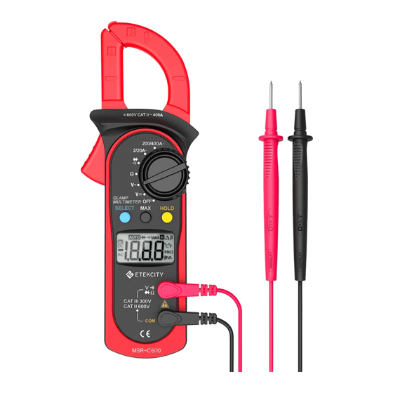
- Page 1 Digital Clamp Multimeter Model No.: MSR-C600...
- Page 2 To avoid electric shock or personal injury, read the “Safety Information” and carefully before using the Meter. MSR-C600 is 2000-count stable, safe and reliable digital clamp multimeter. It is designed with large-scale integrated circuits and A/D converter as the core as well as the overload protection and novel structure, which make it a superb tool for electricians.
- Page 3 Warning range - 2 -...
- Page 4 To avoid any damage to the meter or any accident, do not alter the internal circuit of the Meter randomly. used International Electrical Symbols AC (Alternating Current). DC (Direct Current). AC or DC. Grounding. Double Insulated. Deficiency of Built-In Battery Continuity Test.
-
Page 5: Rotary Switch
The Meter Structure Input Terminals LCD Display Functional Buttons Rotary Switch Trigger: Push/release it to open/close the clamp jaw. Hand Guards: to protect user’s hand from touching the dangerous area. Transformer Jaws: designed to pick up the AC current flowing through the conductor. It could transfer current to voltage. - Page 6 Functional Buttons Not every functional buttons can be used on every rotary switch positions. Rotary Switch Positions Functional Buttons SELECT HOLD Ω 2/20A 200/400A Display Symbols (See Figure 2) Not every functional buttons can be used on every rotary switch positions. ( Figure 2) Symbol Description...
-
Page 7: Measurement Operation
Measurement Operation A. DC Voltage measurement Warning To avoid harms to you or damages to the Meter from eletric shock, do not attempt to black measure voltages higher than 600V AC/DC, ( Figure 3) although readings may be obtained. The DC Voltage ranges are: 200.0mV, 2.000V, 20.00V, 200.0V and 600V. To measure DC voltage, connect the Meter as follows: 1. - Page 8 To measure AC voltage, connect the Meter as follows: 1. Insert the red test lead into the VΩ terminal and the black test lead into the COM terminal. 2. Set the rotary switch to V 3. Connect the test leads across with the object being measured. The measured value shows on the display.
- Page 9 Measuring the tested object that is already removed from the in-line circuit can the in-line circuit can help to obtain a more accurate reading. D.Testing Diodes (See Figure 6) black Warning To avoid damages to the Meter or to the devices under test, disconnect circuit power and discharge all the high-voltage capacitors before testing diodes.
- Page 10 Measuring the tested object that is already removed from the in-line circuit can help to obtain a more accurate reading. (See Figure 7) - 9 -...
-
Page 11: Sleep Mode
F. Measuring AC Current (See Figure 8) trigger Sleep Mode To preserve battery life, the Meter automatically turns off if you do not turn the rotary switch or press any button for around 15 minutes. The Meter can be activated by turning the rotary switch or pressing any button with the following conditions: The Hold function will be cancelled if the Meter is activated by pressing the HOLD button. - Page 12 Specifications Low Battery Indication : Display Opening Tested - 11 -...
- Page 13 Display sinewave RMS( AVG response) - 12 -...
- Page 14 sinewave RMS (AVG response) RMS value Maintenance This section provides basic maintenance information including battery replacement instruction. - 13 -...
- Page 15 Warning Do not attempt to repair or service your Meter unless you are qualified to do so and have the relevant calibration, performance test, and service information. To avoid electrical shock or damage to the Meter, do not get water inside the case. A.
Need help?
Do you have a question about the MSR-C600 and is the answer not in the manual?
Questions and answers