
Related Manuals for ETEKCITY MSR-R500


Summary of Contents for ETEKCITY MSR-R500
-
Page 1: Digital Multimeter
User Manual Digital Multimeter model no.: MSR-R500 Questions or Concerns? support@etekcity.com visit etekcity.com for more products... - Page 2 Safe and Proper Usage Safety Operating Procedures Thank you for purchasing the Etekcity® MSR-R500 Digital Be sure to read, understand and comply with all the Multimeter. Measure DC and AC voltage, current, diode and instructions in this manual audible continuity, and resistance with the convenience of Make sure the test leads are in a safe state.
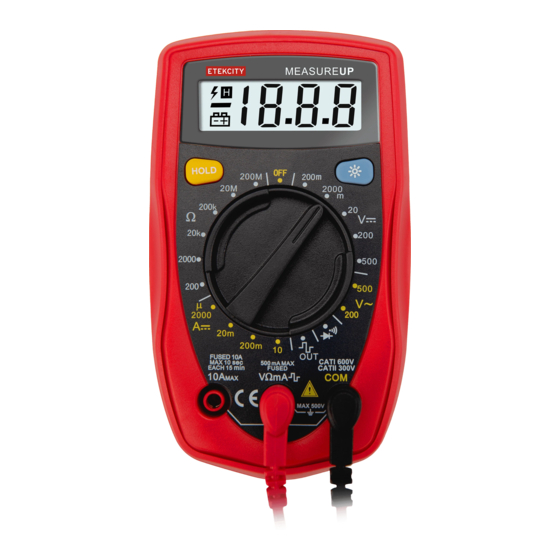
- Page 3 DO NOT change the settings on the rotary switch while Meter Diagram the test leads are measuring a source of power. Use great care when making measurements if the voltages 1. LCD Display are greater than 25VAC rms or 35VDC. These voltages are considered to be a shock hazard.
- Page 4 Battery Type: 1 x 9V Battery NEDA 1604 / 6F22 / 006P General Specifications Overload Display: 1 Dimensions: 130 x 73.5 x 35mm 500V rms Weight: ~156g Maximum Voltage (Including transient overvoltage) DC Voltage Between any Terminals & Grounding Accuracy Overload Range Resolution...
- Page 5 DC Current Diodes and Continuity Measurement Overload Overload Range Resolution Remark Accuracy Range Resolution Protection Protection Display 200µA 0.1µA - - - - - - approximate 315mA, forward voltage 2000µA 1µA 250V fast 250V DC or AC ± (1%+2) drop: 0.5v ~ 0.8v type fuse: 20mA 10µA...
- Page 6 AC Voltage Measurement Measurement Operation (See Figure 2) DC Voltage Measurement AC Voltage Ranges: 200V, 500V Input Impedance: 5 1. Plug the red test lead into the V mA terminal, then plug the black test lead into the COM terminal. 2.
- Page 7 DC Current Measurement NOTE If the value of voltage is unknown, use the maximum WARNING measurement position (10A) and reduce the range until Never attempt an in-circuit current measurement where the proper readings are obtained. voltage between the terminals and ground is greater than Resistance Measurement 60V.
- Page 8 Diode Measurement NOTE In a circuit, a good diode should still produce a forward WARNING voltage drop reading of 0.5V to 0.8V; however, the reverse To avoid damage to the meter and/or the object of voltage drop reading can vary depending on the resistance measurement, disconnect the circuit power and discharge of other pathways between the probe tips.
- Page 9 Square Wave Output Maintenance WARNING To avoid damage to the meter and/or the object of WARNING measurement, do not allow output terminals (red test lead) To avoid false readings, possible electrical shock and/or to surpass 10V. personal injury, replace the battery as soon as the low battery indicator appears on the display.
Need help?
Do you have a question about the MSR-R500 and is the answer not in the manual?
Questions and answers