Advertisement
Quick Links
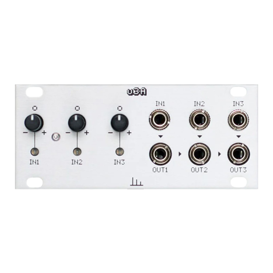
Transient Modules
This guide is for building the u3A module from Transient Modules.
Even if you're an experienced DIYer, please read ALL the steps thoroughly
before starting, as some of them are crucial and others not so obvious.
The u3A kit consists of two boards and all the parts comes in one bag.
See the lists below to identify each one of them easily before start building.
Resistors:
Resistor 10K
Resistor 1K5
Resistor 1K
Capacitors:
100nF
10uF
Headers:
8 pin header male
8 pin header female
Power header
Spacers:
10mm
11mm
Diodes:
1N4007
Hello!
Qty
17
3
3
9
2
2
2
1
1
1
2
ʕ•ᴥ•ʔ
u3A DIY build manual - Version 1.1
Regulators:
7805
Others:
TL074 (SMD)
100KB pots
LEDs bicolor
Jack socket
Knurled nuts
Ferrite beads
Panel
Bottom PCB
Top PCB
Ribbon cable
Screws:
Silver screws
Black screws
Philips 2mm
Hexag 2mm
Qty
1
3
3
3
6
6
2
1
1
1
1
4
2
1
1
Advertisement

Related Manuals for Transient Modules u3A


Summary of Contents for Transient Modules u3A
- Page 1 The u3A kit consists of two boards and all the parts comes in one bag. See the lists below to identify each one of them easily before start building.
- Page 2 Transient Modules u3A DIY build manual - Version 1.1 1. Empty the bag into a bowl or container. This makes it much easier to pick the parts as you need them and you’re a lot less likely to lose anything.
- Page 3 Transient Modules u3A DIY build manual - Version 1.1 8. Solder the 2x 10uF electrolytic capacitors. NOTE! Orientation is vital. The long leg should be positioned in the pad marked with the + symbol. 9. Solder the power header. NOTE!
- Page 4 Transient Modules u3A DIY build manual - Version 1.1 15. Solder the 10 pin male header ensuring it's 90º to the PCB. NOTE! This part is placed at the bottom of the PCB and soldered from the top, as shown on the image.
- Page 5 Transient Modules u3A DIY build manual - Version 1.1 22. Place the 6x jack nuts and make sure that the 3 nuts in the bottom are centered with the silkscreen in the panel. Also make sure the 3 LEDs are positioned through the holes in the panel.
Need help?
Do you have a question about the u3A and is the answer not in the manual?
Questions and answers