Advertisement
Transient Modules
This guide is for building the 4R module from Transient Modules.
Since it is a 2HP module, it's slightly tricky to assemble. Take it easy, and
even if you're an experienced DIYer, please read ALL the steps thoroughly
before starting, as some of them are crucial and others not so obvious.
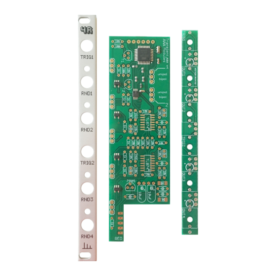
The 4R kit consists of two boards and all the parts comes in one bag.
See the lists below to identify each one of them easily before start building.
Thru Hole Parts
Resistors:
Resistor 100K
Resistor 10K
Resistor 1K
Resistor 24K9
Capacitors:
100nF
22pF
10uF electrolytic
Others:
3 pin header male
Power connector
Ribbon cable
Qty
Thru hole Parts
Regulators:
2
7805
18
8
Transistors:
4
2N3904
Others:
5
LEDs bicolor
4
Jack socket
2
Knurled nuts
Jumper
Panel
7
Bottom PCB
1
Top PCB
1
Silver screws
4R DIY build manual - Version 1.0
Hello!
Qty
1
2
4
6
6
2
1
1
1
2
ʕ•ᴥ•ʔ
SMD Parts
Diodes:
1N5819
Ics:
TL074
Pre-soldered parts:
Atmega328P-AU
LM321
MCP4728
Resistor 4.7K
Resistor 10K
Crystal
100nF capacitor
Ferrite
Qty
2
2
1
4
1
3
1
1
2
1
Advertisement
Table of Contents

Related Manuals for Transient Modules 4R


Summary of Contents for Transient Modules 4R
- Page 1 The 4R kit consists of two boards and all the parts comes in one bag. See the lists below to identify each one of them easily before start building.
- Page 2 Transient Modules 4R DIY build manual - Version 1.0 0. Empty the bag into a bowl or container. This makes it much easier to pick the parts as you need them and you’re a lot less likely to lose anything.
- Page 3 Transient Modules 4R DIY build manual - Version 1.0 4. Solder the 8x 1K resistor. Colour code: brown, black, black, brown, brown. 5. Solder the 4x 24K9 resistor. Colour code: red, yellow, white, red, brown. 6. Solder the 2x 100K resistors.
- Page 4 Transient Modules 4R DIY build manual - Version 1.0 10. Solder the 2x 2N3904 transistors. Labelled T1, T2. NOTE! Make sure you place this part as low as possible. Push down the transistor until it's completely sitting on the PCB, like shown in the image.
- Page 5 Transient Modules 4R DIY build manual - Version 1.0 13. Headers time! Take 2 of them and push the black plastic part all the way down as shown on the frst image. Place the 2x jumpers on the headers in...
- Page 6 Transient Modules 4R DIY build manual - Version 1.0 18. Now you can solder all the LEDs and jack sockets. Once fnished, cut ALL the legs: the ones of the LEDs and also the little ones of all the jack sockets! 19.
- Page 7 Transient Modules 4R DIY build manual - Version 1.0 Something is not working as it should? * Did you like the build manual? * Had problems during the build process? * Do you have any suggestions to make the build process better? *...
Need help?
Do you have a question about the 4R and is the answer not in the manual?
Questions and answers