Advertisement
Transient Modules
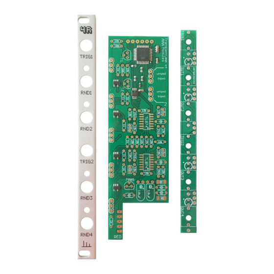
This guide is for building the 4R module from Transient Modules.
Since it is a 2HP module, it may be slightly tricky to assemble it. Take it easy
and even if you're an experienced DIYer, please read ALL the steps
thoroughly before starting the build as some of them may not be so obvious.
The 4R kit consists of two boards and all the parts come in one bag.
See the lists below to identify each one of them easily before start building.
Part
Resistors:
Resistor 100K
Resistor 10K
Resistor 1K
Resistor 24K9
Capacitors:
100nF
22pF
10uF electrolytic
Others:
3 pin angled headers
Power connector
Ribbon cable
Qty
Part
Regulators:
2
7805
18
8
Transistors:
4
2N3904
Others:
7
LEDs bicolor
4
Jack sockets
2
Knurled nuts
Jumper
Panel
7
Bottom PCB
1
Top PCB
1
Silver screws
4R DIY build manual – Version 2.0
Hello!
Qty
1
2
4
6
6
2
1
1
1
2
ʕ•ᴥ•ʔ
Part
Diodes:
1N4007
Ics:
TL074
Pre-soldered parts:
Atmega328P-AU
MCP4728
Resistor 4K7
Resistor 10K
Crystal 16 MHz
Capacitor 100nF
Ferrite
Qty
2
3
1
1
3
1
1
2
1
Advertisement
Table of Contents

Related Manuals for Transient Modules 4R


Summary of Contents for Transient Modules 4R
- Page 1 The 4R kit consists of two boards and all the parts come in one bag. See the lists below to identify each one of them easily before start building.
- Page 2 Transient Modules 4R DIY build manual – Version 2.0 Empty the bag into a bowl or container. This makes it much easier to pick the parts as you need them and you’re a lot less likely to lose anything. 1. Start with the SMD parts. Solder the 3x TL074 ICs.
- Page 3 Transient Modules 4R DIY build manual – Version 2.0 7. Solder the 7x 100nF capacitors, labelled 104. 8. Solder the 2x 10uF electrolytic capacitors. They must be positioned horizontally as shown on the image. NOTE! The long leg should be positioned in the pad marked with the + symbol.
- Page 4 Transient Modules 4R DIY build manual – Version 2.0...
- Page 5 Transient Modules 4R DIY build manual – Version 2.0 19. Join both PCBs. Solder just one leg of any header and check that the boards are 90º. If so, solder the rest of the legs. If not, re-heat that leg to rectify the angle until they're completely perpendicular.
Need help?
Do you have a question about the 4R and is the answer not in the manual?
Questions and answers