Table of Contents
Advertisement
Quick Links
Transient Modules
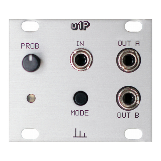
This guide is for building the u1P module from Transient Modules.
Even if you're an experienced DIYer, please read ALL the steps thoroughly
before starting, as some of them may be not so obvious.
The kit consists of two boards and all the parts comes in one paper bag.
See the lists below to identify each one of them easily before starting.
Resistors:
Resistor 1K
Resistor 10K
Resistor 100K
Capacitors:
100nF
10uF
Headers:
10 pin header male
10 pin header female
Power header
Spacers:
M2 - 10mm
Diodes:
4007
4148
Hello!
Qty
3
2
2
3
1
1
1
1
1
1
1
ʕ•ᴥ•ʔ
u1P DIY build manual - Version 1.0
Regulators:
7805
Screws:
Silver screws
Philips 2mm
Others:
Attiny84
14 pin IC socket
100KB potentiometer
2N3904 transistor
LED bicolor
Jack socket
Knurled nuts
Pushbutton + black cap
M2 plastic washer
Panel
Bottom PCB
Top PCB
Ribbon cable
Qty
1
4
2
1
1
1
1
1
3
3
1
1
1
1
1
1
Advertisement
Table of Contents

Related Manuals for Transient Modules u1P


Summary of Contents for Transient Modules u1P
- Page 1 DIY build manual - Version 1.0 Hello! This guide is for building the u1P module from Transient Modules. Even if you're an experienced DIYer, please read ALL the steps thoroughly before starting, as some of them may be not so obvious.
- Page 2 Transient Modules u1P DIY build manual - Version 1.0 1. Empty the bag into a bowl or container. This makes it much easier to pick the parts as you need them and you’re a lot less likely to lose anything.
- Page 3 Transient Modules u1P DIY build manual - Version 1.0...
- Page 4 Transient Modules u1P DIY build manual - Version 1.0 13. Solder the pushbutton and place the black cap on it. A little of pressure must be applied to the black cap in order to make the square shape from the pushbutton to ft into it.
- Page 5 Transient Modules u1P DIY build manual - Version 1.0 18. Join the top PCB and the bottom PCB using the remaining M2 screw. 19. Connect the ribbon cable. The red stripe on the cable must line up with the white line on the module’s power connector.
Need help?
Do you have a question about the u1P and is the answer not in the manual?
Questions and answers