Advertisement
Quick Links
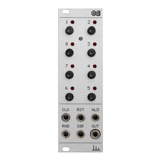
This guide is for building 8S module from Transient Modules.
It is good to have basic soldering skills and to be able to identify electronic components
before starting this kit. In case you're an experienced DIYer, please read all the steps
thoroughly before starting as some of them may be not so obvious.
The 8S kit consists of two boards and all the parts comes in two bags separated.
See the parts list below to identify each one of them easily before start building.
Part
Resistors:
Resistor 100K
Resistor 10K
Resistor 1K
Capacitors:
100nF
22pF
10uF electrolytic
Diodes:
1N4007
Potentiometers:
100KB
100K SMD Trim pot
Sockets:
ICs
Jacks
Qty
Part
Regulators:
6
7805
5
7905
2
Ics:
Atmega328P
8
DG408DJ
2
TL072
2
CD4051 (SMD)
Spacers:
2
10mm spacer
11mm spacer
8
Screws:
1
M2 hexagonal screw
M2 phillips screw
M3 silver screw
3
M3 black screw
6
8S DIY build manual - Version 2.0
Hello!
Qty
1
1
1
1
1
1
1
1
1
1
2
2
ʕ•ᴥ•ʔ
Part
Headers:
8 pin header female
8 pin header male
4x2 pin header female
4x2 pin header male
3 pin angled header
Power connector
Transistors:
2N3904
Others:
LEDs
Knurled nuts
Ferrite bead
Crystal 16MHz
Jumper
Panel
Bottom PCB
Top PCB
Ribbon Cable
Qty
2
2
1
1
2
1
5
8
6
2
1
2
1
1
1
1
Advertisement

Related Manuals for Transient Modules 8S


Summary of Contents for Transient Modules 8S
- Page 1 The 8S kit consists of two boards and all the parts comes in two bags separated. See the parts list below to identify each one of them easily before start building.
- Page 2 8S DIY build manual - Version 2.0 1. Let's begin with the back PCB. Start by emptying the bag of parts into a bowl or container. This makes it much easier to pick them and you’re a lot less likely to lose anything.
- Page 3 8S DIY build manual - Version 2.0 6. Solder the 2x 22pF capacitors (labelled 220). 7. Solder the two 10uF electrolytic capacitors (labelled 10uF). NOTE! Orientation is vital. The long leg should be positioned in the pad marked with the + symbol.
- Page 4 8S DIY build manual - Version 2.0 11. Solder the 7805 regulator. NOTE! Check three times before soldering, 7805 is very similar to 7905 and swapping these two by mistake will fry the module. 12. Solder the 7905 regulator. 13. Solder the 16MHz crystal.
- Page 5 8S DIY build manual - Version 2.0 16. Solder the power header. 17. Solder the three IC Sockets. Make sure the notches in the sockets match the silkscreen. 18. Next take the TL072, DG408, ATMEGA328P and position with the notch on the top face at the same end as the notch in the socket.
- Page 6 8S DIY build manual - Version 2.0 21. Solder the remaining 100nF capacitor. 22. Solder the remaining 1K resistor, labelled “RLEDS”. Colour code: brown, black, black, brown, brown. 23. Solder the two 8 pin male header and the 2x4 pin male header ensuring they're all 90º...
- Page 7 8S DIY build manual - Version 2.0 27. Place the front panel moving a little the parts if necessary. 28. The spacer in the panel must match the hole in the PCB. Join both using the M2 phillips screw. 29. Place the 6 jack nuts and make...
-
Page 8: Testing And Calibration
This new version of the 8S has 2 possible behaviours for the HOLD input. If the jumper is set at HOLD1, as long as the 8S detects a high state at the HLD input, it will hold on that step. If the jumper is set at HOLD2, when there is a high state detected at the HLD input, the 8S will hold the voltage of that speci fic step at the output.
Need help?
Do you have a question about the 8S and is the answer not in the manual?
Questions and answers