
Related Manuals for Epson S5U1C17001H2


Summary of Contents for Epson S5U1C17001H2
- Page 1 CMOS 16-BIT SINGLE CHIP MICROCONTROLLER S5U1C17001H2 User Manual (ICDmini Ver2.0) Rev. 1.1...
- Page 2 Seiko Epson. Seiko Epson reserves the right to make changes to this material without notice. Seiko Epson does not assume any liability of any kind arising out of any inaccuracies contained in this material or due to its application or use in any product or circuit and, further, there is no representation that this material is applicable to products requiring high level reliability, such as, medical products.
- Page 3 Configuration of product number Devices 17xxx 00E1 Packing specifications 00 : Besides tape & reel 0A : TCP BL 2 directions 0B : Tape & reel BACK 0C : TCP BR 2 directions 0D : TCP BT 2 directions 0E : TCP BD 2 directions 0F : Tape &...
-
Page 4: Table Of Contents
6. Flash Programmer Mode ..................23 Preparation for Using Flash Programmer Mode ..............23 6.1.1 fwlp Command ........................23 6.1.1.1 Command format..........................23 6.1.1.2 Command setting example ........................25 6.1.2 fwld Command ........................25 6.1.2.1 Command format..........................25 Seiko Epson Corporation S5U1C17001H2 User Manual (ICDmini Ver2.0) (Rev2.0) - Page 5 Differences between the S5U1C17001H and S5U1C33001H ..........33 9. Troubleshooting....................... 34 10. Specifications......................35 10.1 Electrical Characteristics ...................... 35 Appendix ......................... 36 Initial Validation when Designing a Target System..............36 Revision History ......................38 Seiko Epson Corporation S5U1C17001H2 User Manual (ICDmini Ver2.0)
- Page 6 (gdb) is connected to the target When a low level signal is input to the DSIO pin of the target system When the CPU executes the brk instruction Seiko Epson Corporation S5U1C17001H2 User Manual (ICDmini Ver2.0) (Rev2.0)
-
Page 7: Overview
(2) Section 4.2, Connecting to the Host Computer Install the USB driver before the S5U1C17001H can be used. (3) Section 4.1, Connecting the Target System Please pay particular attention to the Notes. Seiko Epson Corporation S5U1C17001H2 User Manual (ICDmini Ver2.0) (Rev2.0) -
Page 8: Features
*2: Reference values for data download speed are published on the user’s site for each S1C processor model. *3: If connecting a 10-pin connector, refer to “4.1.1.1 Connecting to S1C33 processor 10-pin connector.” Seiko Epson Corporation S5U1C17001H2 User Manual (ICDmini Ver2.0) -
Page 9: Operating Environment
Operating Environment As the host computer, the S5U1C17001H uses a PC with a USB port (USB 1.1) available. For details concerning operating systems, refer to “Operating Environment” in the S5U1C17001C Manual. Seiko Epson Corporation S5U1C17001H2 User Manual (ICDmini Ver2.0) (Rev2.0) -
Page 10: Components Included With Package
S5U1C33001C Manual Included with S1C33 Family C Compiler Package S5U1C17001H User Manual (ICDmini Ver2.0) This manual can be downloaded from the Seiko Epson Electronic Devices website. Figure 2.1 S5U1C17001H Package Contents Seiko Epson Corporation S5U1C17001H2 User Manual (ICDmini Ver2.0) -
Page 11: Name And Function Of Each Part
Otherwise, there is a risk of damaging the chip due to overvoltage. The V pin should be left open if a connector pin is provided on the target board without using the Flash programming voltage. Seiko Epson Corporation S5U1C17001H2 User Manual (ICDmini Ver2.0) (Rev2.0) -
Page 12: Dip Switch
Enabling the connection test (SW6) Table 3.1.3.4 SW6 Settings Setting OPEN () Omit connection test (default) ON () Execute connection test The connection test is a communication diagnostic feature at start up of the debugger. Seiko Epson Corporation S5U1C17001H2 User Manual (ICDmini Ver2.0) - Page 13 This must never be used with S1C processors for which usage instructions are not provided in the technical manual when supplying a voltage as the Flash programming power supply from the S5U1C17001H to the target. Otherwise, there is a risk of damaging the chip due to overvoltage. Seiko Epson Corporation S5U1C17001H2 User Manual (ICDmini Ver2.0) (Rev2.0)
-
Page 14: Brk In Pin
Pin capable of supplying a 3.3 V power supply (max. 100 mA) to the target system. 3.1.7 1.8 V Output Pin Pin capable of supplying a 1.8 V power supply (max. 100 mA) to the target system. Seiko Epson Corporation S5U1C17001H2 User Manual (ICDmini Ver2.0) -
Page 15: Right Side Panel
USB port, or use an AC adapter (with USB 5 V output) capable of supplying power to the USB cable. If using an AC adapter, set the S5U1C17001H mode to be used and confirm beforehand that erasing and writing is possible as desired. Seiko Epson Corporation S5U1C17001H2 User Manual (ICDmini Ver2.0) (Rev2.0) -
Page 16: Top Panel
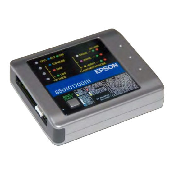
Illuminates as shown below when ICD mode is selected using SW2 and SW3. Table 3.3.1.1.2 LED2 Status S1C17 S1C33 LED status Status (blue) The S5U1C17001H is being operated in ICD mode. Seiko Epson Corporation S5U1C17001H2 User Manual (ICDmini Ver2.0) -
Page 17: In Flash Programmer Mode
(blinking The Flash memory is being erased. white) (green) The Flash erasing operation has completed normally. (OK) (red) A Flash erase error has occurred. (ERR) Seiko Epson Corporation S5U1C17001H2 User Manual (ICDmini Ver2.0) (Rev2.0) - Page 18 (2) “-s” option was set multiple times by the “fwlp” command. – Write-back setting error (ERR) (blinking (blinking (blinking red) red) yellow) (1) “-b” option was set by the “fwlp” command, but the setting Seiko Epson Corporation S5U1C17001H2 User Manual (ICDmini Ver2.0)
-
Page 19: Reset/Restart Switch
Issues a hardware reset to the S5U1C17001H. Note: When a DIP switch setting is changed, it will take effect by pressing the RESET/START switch (in both ICD and Flash programmer modes). Seiko Epson Corporation S5U1C17001H2 User Manual (ICDmini Ver2.0) (Rev2.0) -
Page 20: Connections
The 4-pin connector does not have a projection for preventing reverse insertion. Check the cable color (blue) of pin 1 to be sure the insertion of connector is proper when connecting it to the target system. Seiko Epson Corporation S5U1C17001H2 User Manual (ICDmini Ver2.0) -
Page 21: Connecting To The S1C33 Processor 10-Pin Connector
Note: Connect the S5U1C17001H to the S1C processor ensuring that the distance between them is as short as possible (no more than 20 cm). Shielding the signal wire using GND is also effective in ensuring stable operation. Seiko Epson Corporation S5U1C17001H2 User Manual (ICDmini Ver2.0) (Rev2.0) -
Page 22: Flash Programming Power Supply Connector
In addition to 3.3 V and 1.8 V, the S5U1C17001H is capable of interfacing with the target system using the voltage (1.0 to 5.5 V) input from the target system. To use this function, set SW4 to ON and input the target voltage to the TARGET VCC IN pin. Seiko Epson Corporation S5U1C17001H2 User Manual (ICDmini Ver2.0) -
Page 23: Flash Programming Voltage Output (Flash Vcc Out)
Note: Refer to the individual technical manual for each model to determine whether the Flash programming voltage supply is required. Do not use this voltage unless mentioned in the technical manual. Otherwise, there is a risk of damaging the S1C processor due to overvoltage. Seiko Epson Corporation S5U1C17001H2 User Manual (ICDmini Ver2.0) (Rev2.0) -
Page 24: Connecting To The Host Computer
(1) First time the S5U1C17001H is connected to the host computer with the USB cable, the dialog box shown below will be displayed. When S1C17 processor is selected When S1C33 processor is selected Figure 4.2.2.1 New Hardware Detection Start Screen Seiko Epson Corporation S5U1C17001H2 User Manual (ICDmini Ver2.0) - Page 25 When S1C17 processor is selected When S1C33 processor is selected Figure 4.2.2.3 Driver Installation Complete Screen Note: If the window above is not displayed correctly, try to reinstall the USB driver. Seiko Epson Corporation S5U1C17001H2 User Manual (ICDmini Ver2.0) (Rev2.0)
-
Page 26: Icd Mode
(green) If the LEDs appear as shown below, repeat the procedure from step (1). LED1 (blue) or (green) LED2 (blue) LED3 (red) (green) or (out) LED4 Seiko Epson Corporation S5U1C17001H2 User Manual (ICDmini Ver2.0) -
Page 27: When The Target Rst Out Signal Is Connected
For more details of debugger commands and debugger operations, refer to the “S5U1C17001C Manual (S1C17 Family C compiler package)” or “S5U1C33001C Manual (S1C33 Family C compiler package).” Note: Before disconnecting the S5U1C17001H from the host computer, be sure to terminate the debugger. Seiko Epson Corporation S5U1C17001H2 User Manual (ICDmini Ver2.0) (Rev2.0) -
Page 28: Flash Programming Voltage Setting
(gdb) c17 flvs ················· Cancel Flash programming voltage output Stop output flash voltage. For information on debugger (gdb) operations and other commands, refer to the “S5U1C17001C Manual (S1C17 Family C Compiler Package).” Seiko Epson Corporation S5U1C17001H2 User Manual (ICDmini Ver2.0) -
Page 29: Flash Programmer Mode
The following options (v, s, b, n, t) can be specified in the comment section only when the S1C17 processor has been selected. Function Flash programming voltage control option Specifying the “-v” option within the comment section allows the flash programming voltage to be set. Seiko Epson Corporation S5U1C17001H2 User Manual (ICDmini Ver2.0) (Rev2.0) - Page 30 Option settings may use either upper case or lower case. An option error will occur if the same option is set more than once. Seiko Epson Corporation S5U1C17001H2 User Manual (ICDmini Ver2.0)
-
Page 31: Command Setting Example
When S1C17 is selected Example: With S1C processor that supports chip erasing To erase all sectors and load user_program.saf from Flash 0x8000 address (gdb) c17 fwld user_ program.saf 0 0 0x8000 Seiko Epson Corporation S5U1C17001H2 User Manual (ICDmini Ver2.0) (Rev2.0) -
Page 32: Operations In Flash Programmer Mode
USB port of the host computer or to a 5 V AC USB adapter (see “3.2 Right Side Panel”) to supply power. In the Flash programmer mode, only power is required from the USB cable and there is no communication with the host computer. Seiko Epson Corporation S5U1C17001H2 User Manual (ICDmini Ver2.0) - Page 33 (8) Return to Step (4) to continue the same Flash operation. Return to Step (1) to change the Flash operation. When finishing Flash programming, disconnect the USB cable and set the DIP switch back to ICD mode. Seiko Epson Corporation S5U1C17001H2 User Manual (ICDmini Ver2.0) (Rev2.0)
-
Page 34: Firmware Update
The S5U1C17001H has a firmware update function using the debugger (gdb). T he following shows the procedure to update the S5U1C17001H firmware. The firmware can also be updated using the firmware update package available on the Epson microcontroller users’ site. - Page 35 LEDs illuminate in sequence LED1 LED2 LED3 After which: LED1 (blue) or (green) LED2 (green: successfully erased) LED3 (green: successfully written or verified) LED4 (green: firmware update successfully completed) Seiko Epson Corporation S5U1C17001H2 User Manual (ICDmini Ver2.0) (Rev2.0)
- Page 36 LED4 (red: firmware update failed) If this error occurs, the S5U1C17001H may be faulty. Please contact a Seiko Epson sales office. (8) Set SW7 to “OPEN” and press the RESET/START switch again. The firmware restarts. If firmware updating failed, the original firmware restarts.
-
Page 37: Precautions
S1C processor on the target system is executing the target program in normal mode. It will be enabled again when the S1C processor enters debug mode. Seiko Epson Corporation S5U1C17001H2 User Manual (ICDmini Ver2.0) (Rev2.0) -
Page 38: Differences From The Actual Ic
S1C processor into debug mode. Although this signal is pulled up through about 100 kinternally, when not debugging, we recommend either removing the 33 resistor to reduce noise and other problems or pulling this line up to the V level. Seiko Epson Corporation S5U1C17001H2 User Manual (ICDmini Ver2.0) -
Page 39: Differences Between The S5U1C17001H And S5U1C33001H
S5U1C17001H when the target system power supply is turned on or off. Differences between the S5U1C17001H and S5U1C33001H The trace function cannot be used if S1C33 is selected with the S5U1C17001H. Seiko Epson Corporation S5U1C17001H2 User Manual (ICDmini Ver2.0) (Rev2.0) -
Page 40: Troubleshooting
Use the supplied cable. If it cannot be used then use extension cables that are as short as possible and shield them in order to avoid occurrence of low-level noise on the DSIO signal. Seiko Epson Corporation S5U1C17001H2 User Manual (ICDmini Ver2.0) -
Page 41: Specifications
* A stable power supply (+5.0 V) must be supplied via the USB connector. Table 10.1.2 Flash Programming Voltage Specifications Selected processor Item Unit S1C17 Current – – Voltage – S1C33 Current – – Voltage – – Seiko Epson Corporation S5U1C17001H2 User Manual (ICDmini Ver2.0) (Rev2.0) -
Page 42: Appendix
Normal LED1 (blue) or (green) LED2 (blue) LED3 (red) LED4 (green) Input High High signals to the #RESET pin. (This resets the S1C processor.) Seiko Epson Corporation S5U1C17001H2 User Manual (ICDmini Ver2.0) - Page 43 (blue) or (green) LED2 (blue) LED3 (red) (out) LED4 Press the RESET/START switch on the S5U1C17001H once and input High High signals to the #RESET pin. Seiko Epson Corporation S5U1C17001H2 User Manual (ICDmini Ver2.0) (Rev2.0)
-
Page 44: Revision History
AC adapter usage description changed. Pages 12-13 fwlp command option -s, -b, -n, and -t descriptions added. Pages 23-27 fwlp command option -s, -b, -n, and -t descriptions added. Pages 28-30 Firmware update function changed. Seiko Epson Corporation S5U1C17001H2 User Manual (ICDmini Ver2.0) - Page 45 EPSON HONG KONG LTD. Unit 715-723, 7/F Trade Square, 681 Cheung Sha Wan Road, Kowloon, Hong Kong. Phone: +852-2585-4600 FAX: +852-2827-4346 EPSON TAIWAN TECHNOLOGY & TRADING LTD. 14F, No. 7, Song Ren Road, Taipei 110, TAIWAN Phone: +886-2-8786-6688 FAX: +886-2-8786-6660 EPSON SINGAPORE PTE., LTD.
- Page 46 Mouser Electronics Authorized Distributor Click to View Pricing, Inventory, Delivery & Lifecycle Information: Epson S5U1C33001H1400...
Need help?
Do you have a question about the S5U1C17001H2 and is the answer not in the manual?
Questions and answers