Table of Contents
Advertisement
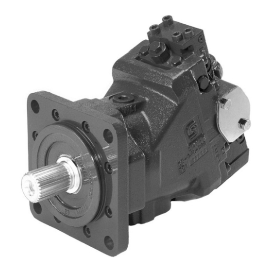
HYDRAULIC PUMP
SAUER DANFOSS SERIES 51 BENT AXIS HYDRAULIC MOTOR
1
. . . . . . . . . . . . . . . . . . . . . . . . . . . . . . . . . . . . . . . . . . . . . . . . . . . . . . . . . . . . . . . . . . . . . . . . . . . . .
1.1
2
3
4
5
6
6.1
6.2
6.3
6.4
6.5
6.5.1
6.5.2
6.5.3
6.5.4
6.5.5
6.5.6
6.5.7
6.5.8
6.5.9
6.5.10
6.5.11
6.6
7
. . . . . . . . . . . . . . . . . . . . . . . . . . . . . . . . . . . . . . . . . . . . . . . . . . . . . . . . . . . . . . . . . . . . . .
. . . . . . . . . . . . . . . . . . . . . . . . . . . . . . . . . . . . . . . . . . . . . . . . . . . . . . . . . . . . . . . . . . . .
. . . . . . . . . . . . . . . . . . . . . . . . . . . . . . . . . . . . . . . . . . . . . . . . . . . . . . . . . . . . . . . . .
. . . . . . . . . . . . . . . . . . . . . . . . . . . . . . . . . . . . . . . . . . . . . . . . . . . . . . . . . . . . . . . . . . . . .
. . . . . . . . . . . . . . . . . . . . . . . . . . . . . . . . . . . . . . . . . . . . . . . . . . . . . . . . . . .
. . . . . . . . . . . . . . . . . . . . . . . . . . . . . . . . . . . . . . . . . . . . . . . . . . . . . . . . . . . . . . . .
. . . . . . . . . . . . . . . . . . . . . . . . . . . . . . . . . . . . . . . . . . . . . . . . . . . . . . .
. . . . . . . . . . . . . . . . . . . . . . . . . . . . . . . . . . . . . . . . . . . . . . . . . . . . . . . . . .
. . . . . . . . . . . . . . . . . . . . . . . . . . . . . . . . . . . . . . . . . . . . . . . . . . . . . . . . . . . . . . . . . . . . . . .
. . . . . . . . . . . . . . . . . . . . . . . . . . . . . . . . . . . . . . . . . . . . . . . . . . . . . . . . .
. . . . . . . . . . . . . . . . . . . . . . . . . . . . . . . . . . . . . . . . . . . . . . . . . . . . . .
. . . . . . . . . . . . . . . . . . . . . . . . . . . . . . . . . . . . . . . . . . . . . . . . . . . . . . . . . . . . . . . . .
. . . . . . . . . . . . . . . . . . . . . . . . . . . . . . . . . . . . . . . . . . . . . . . . . . . . . . . . . . . . . . . . . . . . . . . . .
. . . . . . . . . . . . . . . . . . . . . . . . . . . . . . . . . . . . . . . . . . . . . . . . . . . . . . . . . . . . . . . . . . . . . . . .
. . . . . . . . . . . . . . . . . . . . . . . . . . . . . . . . . . . . . . . . . . . . . . . . . .
. . . . . . . . . . . . . . . . . . . . . . . . . . . . . . . . . . . . . . . . . . . . . . . . .
. . . . . . . . . . . . . . . . . . . . . . . . . . . . . . . . . . . . . . . . . . . . . . .
. . . . . . . . . . . . . . . . . . . . . . . . . . . . . . . . . . . . . . . . . .
. . . . . . . . . . . . . . . . . . . . . . . . . . . . . . . . . . . . . . . .
. . . . . . . . . . . . . . . . . . . . . . . . . . . . . . . . . . . . . . . . .
. . . . . . . . . . . . . . . . . . . . . . . . . . . . .
. . . . . . . . . . . . . . . . . . . . . . . . . . . . . . . . . . . . . .
. . . . . . . . . . . . . . . . . . . . . . . . . . . . . . . . . . . . . . . . . . . . . .
. . . . . . . . . . . . . . . . . . . . . . . . . . . . . . . . . . . . . . . . . . . . . .
GROUP 3025
2
3
4
6
7
7
8
8
9
10
11
12
12
13
15
16
17
18
21
22
23
24
26
27
28
3025- - 9A, Page 1
Advertisement
Table of Contents

Related Manuals for Sauer Danfoss 51 Series


Summary of Contents for Sauer Danfoss 51 Series
-
Page 1: Table Of Contents
HYDRAULIC PUMP GROUP 3025 SAUER DANFOSS SERIES 51 BENT AXIS HYDRAULIC MOTOR INTRODUCTION................ -
Page 2: Introduction
GROUP 3025 HYDRAULIC PUMP 1 INTRODUCTION. Many repairs and adjustments can be performed with the Series 51 motor mounted to the gear reduction unit on the blower, if the motor is throughly cleaned before This group provides information for servicing the Series beginning any procedures. -
Page 3: Specification Sheet
HYDRAULIC PUMP GROUP 3025 Series 51 Motor Specification Sheet Model Code: 51V 080 R S1 N EQ A2 K Y G0 NNN 030 AA E4 85 31 Series 51 Bent Axis Motor SAE Flange Mount 080 = 80cc/rev (4.92 cu in/rev) Maximum Displacement Side Ports 14 tooth 12/24 Pith Spline Shaft No Maximum Displacement Limiter... -
Page 4: General Description
GROUP 3025 HYDRAULIC PUMP 2 GENERAL DESCRIPTION An electrohydraulic control is mounted on the motor end cap to control the servo piston and the motor The Series 51 variable displacement hydraulic motor displacement. Servo pressure oil is supplied externally uses spherical pistons and piston rings. The angle from the hydraulic reservoir pump. - Page 5 HYDRAULIC PUMP GROUP 3025 Type EQ electrohydraulic proportional control (Fig. 2) consists of a valve block and pressure control pilot (PCP) valve mounted on the multi--function block. The valve block incorporates a pilot piston with centering springs. A pin transmits force from the pilot piston to the control spool in the end cap.
-
Page 6: Test Gauge Installation
GROUP 3025 HYDRAULIC PUMP 3 TEST GAUGE INSTALLATION Pressure gauge readings used troubleshooting problems with Series 51 motor or system problems. Figure 3 details port location. M3 Gauge Port M2 Gauge Port M1 Gauge Port M5 Gauge Port Figure 3. EQ Model Control Gauge Port locations. Port Designation &... -
Page 7: Start--Up Procedure
HYDRAULIC PUMP GROUP 3025 4 START ---UP PROCEDURE Slowly rotate the torque hub by hand, or “jog” the pump until charge pressure starts to rise. Start the Series 51 The start--up procedure must be followed when starting pump and run at the lowest possible RPM until charge up a new Series 51 installation or when restarting an pressure is established. -
Page 8: Component Adjustments
GROUP 3025 HYDRAULIC PUMP 6 COMPONENT ADJUSTMENTS the setting of the pump charge relief valve (measured with the pump in the “neutral” or zero---angle position). This setting assumes WARNING a reservoir temperature of 50 C (122 and is referenced to case pressure. It is recommended that the auger be disconnected from the torque hubs Adjust the charge pressure by loosening the... -
Page 9: Minimum Displacement Limiter Adjustment
HYDRAULIC PUMP GROUP 3025 Minimum Displacement Limiter Adjustment screw clockwise to increase the minimum displacement, or rotate the adjusting screw counterclockwise to decrease the minimum WARNING displacement of the motor. Care should be taken in adjusting displacement limiters to avoid un- desirable speed conditions. -
Page 10: Maximum Displacement Limiter Adjustment
GROUP 3025 HYDRAULIC PUMP Maximum Displacement Limiter Adjustment Remove the minimum angle servo cover and o---rings. Remove the displacement WARNING limiter screw with an 8 mm internal hex wrench (Fig. 8) Care should be taken in adjusting displacement limiters to avoid un- desirable speed conditions. -
Page 11: Displacement Control Adjustments
HYDRAULIC PUMP GROUP 3025 Displacement Control Adjustments: Increase the control start current. An in- Electro -- hydraulic Proportional Control Type EQ crease in minimum angle servo pressure will be noted as the motor displacement starts NOTE to decrease. Adjust the control start current by loosening A change in motor displacement the lock nut using a 10 mm hex wrench and can be detected by providing a... -
Page 12: Minor Repair And Replacement
GROUP 3025 HYDRAULIC PUMP Minor Repair and Replacement 6.5.1 General Cleanliness is a primary means of insuring satisfactory It is recommended that all gaskets and o--rings be motor life, on either new or repaired units. Cleaning replaced. All gasket sealing surfaces must be cleaned parts using a solvent wash and air drying is adequate. -
Page 13: Shaft Seal Replacement
HYDRAULIC PUMP GROUP 3025 6.5.2 Shaft Seal Replacement (SAE Flange Configuration) Replacement of the lip type shaft seals requires removal of the Type 51 motor from the torque hub unit. Refer to Groups 3059 and 3001 for removal information. Remove the screws holding the flange to the housing using a 6 mm internal hex wrench (Fig 11). - Page 14 GROUP 3025 HYDRAULIC PUMP Install a new o---ring on the flange. Lubricate the flange o---ring and the inner diameter of the seal with petroleum jelly. Wrap the spline or key end of the shaft with plastic film to prevent damaging the new seal during installation.
-
Page 15: Loop Flushing Shuttle Valve Replacement
HYDRAULIC PUMP GROUP 3025 6.5.3 Loop Flushing Shuttle Valve Replacement Remove the hex plugs from both sides of the end cap (Fig. 17). Figure 19. Loop Flushing Shuttle Valve Components Install flushing valve spool in end cap (Fig. 20). Install the spring seat washers on each end of the spool. -
Page 16: Charge Pressure Relief Valve Replacement
GROUP 3025 HYDRAULIC PUMP 6.5.4 Charge Pressure Relief Valve Replacement NOTE Before removing the screw adjust- able relief valve plug, it is recom- mended that you mark the plug, lock nut and end cap to allow the original adjustment to be maintained upon reassembly. -
Page 17: Minimum Angle Servo Cover Replacement
HYDRAULIC PUMP GROUP 3025 6.5.5 Minimum Angle Servo Cover Replacement Remove the o---rings between the cover and end cap and discard. CAUTION Coat new o---rings with petroleum jelly and Before removing the cover, through- install on the end cap. Install the cover onto ly clean the external surfaces of the the end cap torquing to 58 ft. -
Page 18: Electrohydraulic Proportional Control Service (Type Eq)
GROUP 3025 HYDRAULIC PUMP 6.5.6 Electrohydraulic Proportional Control (Type EQ) Service Remove the Pressure Control Pilot (PCP) valve (Fig. 27) as detailed in paragraph 6.5.7. Figure 29. EQ Control Housing Removal Remove the valve housing with the pilot pis- ton from the multi---function block. Remove the o---rings from the valve hous- ing. - Page 19 HYDRAULIC PUMP GROUP 3025 Install the pilot piston pin in the multi---func- tion block (Fig. 31). Figure 33. Pilot Piston Installation Figure 31. Pilot Pin Installation (11) Install the small spring in the outer end of the pilot piston (Fig. 34). Position the valve housing (with o---rings installed) on the multi---function block (Fig.
- Page 20 GROUP 3025 HYDRAULIC PUMP (13) Install the PCP valve (Fig. 36). Torque the four screws to 48 in. lbs. (54 Nm). Figure 35. Control Cover Installation Figure 36. Install PCP Valve 3025- -9A, Page 20...
-
Page 21: Pressure Control Pilot Valve
HYDRAULIC PUMP GROUP 3025 6.5.7 Pressure Control Pilot (PCP) Valve Remove the four (4) screws holding the PCP valve to the control valve housing with a 4mm internal hex wrench (Fig.37). Figure 38. PCP O- -Rings Position the PCP on the control valve hous- ing (Fig. -
Page 22: Multi--Function Block Removal And Installation
GROUP 3025 HYDRAULIC PUMP 6.5.8 Multi-- Function Block Removal and a filter screen installed in the end cap pas- Installation sage leading to the valve spool sleeve. If screens are removed due to damage or for Remove the EQ Proportional Control as de- cleaning, the replacement screens must be scribed in paragraph 6.5.6. -
Page 23: Servo Pressure Supply Shuttle Spool
HYDRAULIC PUMP GROUP 3025 Figure 46. Supply Spool Plug Removal NOTE Figure 44. Multi- -Function Block Installation If a pressure compensator valve block is installed, the opposite end of the shuttle spool bore in the mul- Torque the mounting screws to 58 ft. lbs (78 ti-- function valve is plugged with an Nm). -
Page 24: Pcor Brake Pressure Defeat Spool
GROUP 3025 HYDRAULIC PUMP The shuttle ball in the spool must be free to 6.5.10 PCOR Brake Pressure Defeat Spool move. Remove the PCOR defeat spool bore plugs or fittings with a hex wrench (Fig.50). Install the shuttle spool into the multi---func- tion block (Fig 48). - Page 25 HYDRAULIC PUMP GROUP 3025 Install the spool stop plugs into the multi--- function block (Fig. 54). Torque the stop plugs to 4 ft. lbs (6 Nm). Figure 52. Multi- -function Block with PCOR Defeat Spool Components Install the PCOR defeat spool into its bore in the multi---function block (Fig 53).
-
Page 26: Control Orifices
GROUP 3025 HYDRAULIC PUMP 6.5.11 Control Orifices -- Orifices are installed in the motor end cap to regulate oil flow to the servo control valve and the servo piston. These orifices can be re- moved to check for damage or plugging. To gain acccess to these orifices, remove the three (3) plugs located on the motor end cap nearest the multi---function block, using... -
Page 27: Torque Values
HYDRAULIC PUMP GROUP 3025 Torque Values -- Plugs and Fittings Any plugs or fittings that were removed from the unit during servicing that do not have specific torque values set forth in the service instructions should be torqued according to the following chart: 3025- - 9A, Page 27... -
Page 28: Troubleshooting
GROUP 3025 HYDRAULIC PUMP 7 TROUBLESHOOTING 3025- -9A, Page 28... - Page 29 HYDRAULIC PUMP GROUP 3025 3025- - 9A, Page 29...
- Page 30 GROUP 3025 HYDRAULIC PUMP 3025- -9A, Page 30...
Need help?
Do you have a question about the 51 Series and is the answer not in the manual?
Questions and answers