Sign In
Upload
Download
Table of Contents
Contents
Add to my manuals
Delete from my manuals
Share
URL of this page:
HTML Link:
Bookmark this page
Add
Manual will be automatically added to "My Manuals"
Print this page
×
Bookmark added
×
Added to my manuals
Manuals
Brands
Sauer Danfoss Manuals
Water Pump
20 Series
Service manual
Sauer Danfoss 20 Series Service Manual
Axial piston pumps
Hide thumbs
Also See for 20 Series
:
Service manual
(28 pages)
1
2
Table Of Contents
3
4
5
6
7
8
9
10
11
12
13
14
15
16
17
18
19
20
21
22
23
24
25
26
27
28
29
30
31
32
33
34
35
36
page
of
36
Go
/
36
Contents
Table of Contents
Troubleshooting
Bookmarks
Table of Contents
Introduction and Description
Table of Contents
Model Code
Recommended Tools and Installation
List of Tools Necessary for Minor Repairs and Maintenance of Units of All Sizes
Additional Tools List for Complete Stripping of Units
Measuring Instruments
Trouble Shooting, Gauge Installation and Information
Start-Up Procedure
Preconditions for Trouble-Free Operation
First-Time Operation
Plumbing Installation (Variable Displac. Pump - Fixed Displac. Motor)
System Circuit Description
System Maintenance
Inlet Filter (between Fluid Reservoir and Charge Pump)
Changing the Oil
Leak Test
Cleanliness
Checking of the Oil Level
Recommended Oils
Trouble Shooting
Transmission Operates in One Direction Only
System Response Is Sluggish
Neutral Difficult or Impossible to Find
System will Not Operate in Either Direction
Inspection Instructions
Checking the Charge Pressure
Checking the Charge Pump
Checking the Charge Check Valves
Checking the Servo Valve (Control Valve)
Disassembly and Assembly
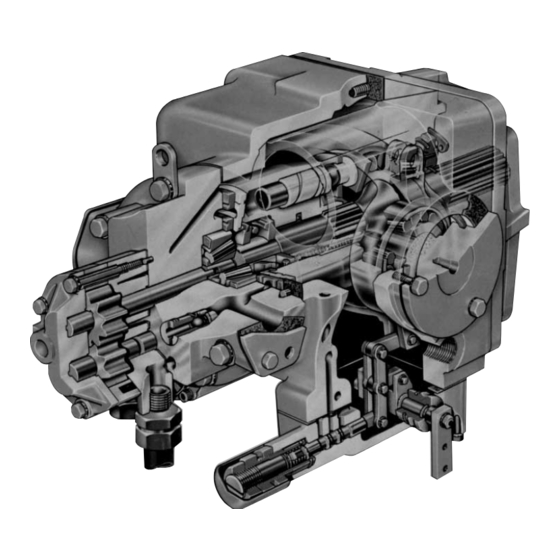
Sectional View
Exploded View
Minor Repairs
Preparation for Assembly
Mounting Block
Changing the Shaft Seal Disassembly
Changing the Shaft Seal Assembly
Changing the Charge Pump and the Charge Check Valves
Changing the Servo Valve (Control Valve)
Major Repairs
Changing the Valve and Bearing Plate Disassembly
Changing the Valve and Bearing Plate Assembly
Changing the Cylinder Block Kit Disassembly
Changing the Cylinder Block Kit Assembly
Changing the Swash Plate and Servo Piston Disassembly
Changing the Swash Plate and Servo Piston Assembly
Changing the Pump Shaft
Installation Torque Values
Advertisement
Quick Links
1
Model Code
Download this manual
Series 20
Axial Piston Pumps
Service Manual and
Repair Instructions
Table of
Contents
Previous
Page
Next
Page
1
2
3
4
5
Advertisement
Table of Contents
Troubleshooting
Trouble shooting, gauge installation and information
6
Trouble shooting
12
Need help?
Do you have a question about the 20 Series and is the answer not in the manual?
Ask a question
Questions and answers
Related Manuals for Sauer Danfoss 20 Series
Water Pump Sauer Danfoss 20 Series Service Manual
Axial piston motors (28 pages)
Water Pump Sauer Danfoss Series S90 180 cc Service & Parts Manual
Axial piston pump (52 pages)
Water Pump Sauer Danfoss 45 Series Service Manual
Frame g open circuit axial piston pumps (28 pages)
Water Pump Sauer Danfoss CP180 Assembly Manual
Cp series gear pumps (33 pages)
Water Pump Sauer Danfoss H1 Technical Information
Axial piston pump size 045/053, single (44 pages)
Water Pump Sauer Danfoss 51 Series Manual
(30 pages)
Water Pump Sauer Danfoss 40 Series Technical Information
Axial piston pumps (72 pages)
Water Pump Sauer Danfoss SPV2 Series Service Manual
Axial piston pumps (36 pages)
This manual is also suitable for:
Spv2 series
Table of Contents
Save PDF
Print
Rename the bookmark
Delete bookmark?
Delete from my manuals?
Login
Sign In
OR
Sign in with Facebook
Sign in with Google
Upload manual
Upload from disk
Upload from URL


Need help?
Do you have a question about the 20 Series and is the answer not in the manual?
Questions and answers