Table of Contents
Advertisement
Quick Links
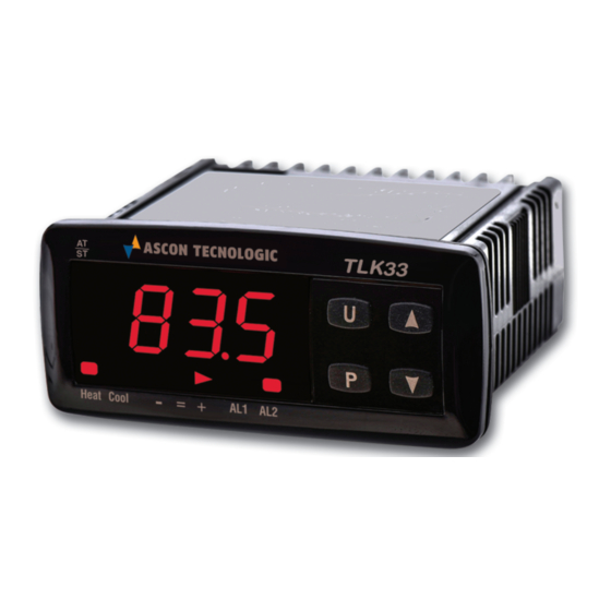
TLK 33
DIGITAL MICROPROCESSOR-
BASED ELECTRONIC
CONTROLLER WITH DIRECT
COMMAND FOR PELTIER
DEVICE
OPERATING INSTRUCTIONS
13/10 - Code: ISTR_M_TLK33_E_02_--
ASCON TECNOLOGIC S.r.l.
Viale Indipendenza 56
27029 Vigevano (PV) ITALY
TEL.: +39 0381 69871 - FAX: +39 0381 698730
http:\\www.ascontecnologic.com
e-mail: info@ascontecnologic.com
FOREWORD
This
manual
necessary for the product to be installed
correctly
maintenance
recommend that the utmost attention is paid to
the following instructions and to save it.
This
document
is
the
Tecnologic S.r.l. which forbids any reproduction and
divulgation , even in part, of the document, unless expressly
authorized.
Ascon Tecnologic S.r.l. reserves the right to make any formal
or functional changes at any moment and without any notice.
Whenever a failure or a malfunction of the device may cause
dangerous situations for persons, thing or animals, please
remember that the plant has to be equipped with additional
devices which will guarantee safety.
Ascon Tecnologic S.r.l. and its legal representatives do not
assume any responsibility for any damage to people, things or
animals deriving from violation, wrong or improper use or in
any case not in compliance with the instrument's features.
contains
the
information
and
also
instructions
and
use;
we
exclusive
property
of
ASCON TECNOLOGIC - TLK33 - OPERATING INSTRUCTIONS - PAG. 1
INDEX
1
INSTRUMENT DESCRIPTION
1.1
GENERAL DESCRIPTION
1.2
FRONT PANEL DESCRIPTION
2
PROGRAMMING
2.1
FAST PROGRAMMING OF SET POINT
2.2
SELECTION OF CONTROL STATE AND PARAMETER
PROGRAMMING
2.3
PARAMETER PROGRAMMING LEVELS
2.4
CONTROL STATES
2.5
ACTIVE SET POINT SELECTION
3
INFORMATION ON INSTALLATION AND USE
3.1
PERMITTED USE
3.2
MECHANICAL MOUNTING
3.3
ELECTRICAL CONNECTIONS
3.4
ELECTRICAL WIRING DIAGRAM
4
FUNCTIONS
4.1
MEASURING AND VISUALIZATION
4.2
DOUBLE ACTION PID CONTROL
4.3
AUTO-TUNING AND SELF-TUNING FUNCTIONS
4.4
REACHING OF SET POINT AT CONTROLLED SPEED
AND AUTOMATIC COMMUTATION BETWEEN TWO
SET POINTS
4.5
ALARM OUTPUTS FUNCTIONS
4.6
FUNCTION OF KEY "U"
4.7
DIGITAL INPUTS
4.8
RS 485 SERIAL INTERFACE
4.9
PARAMETERS CONFIGURATION BY A01
5
PROGRAMMABLE PARAMETERS TABLE
6
PROBLEMS , MAINTENANCE AND GUARANTEE
6.1
ERROR SIGNALLING
6.2
CLEANING
6.3
GUARANTEE AND REPAIRS
7
TECHNICAL DATA
7.1
ELECTRICAL DATA
7.2
MECHANICAL DATA
7.3
MECHANICAL DIMENSIONS, PANEL CUT- OUT AND
MOUNTING
7.4
FUNCTIONAL DATA
7.5
MEASUREMENT RANGE TABLE
7.6
INSTRUMENT ORDERING CODE
1 - INSTRUMENT DESCRIPTION
1.1 - GENERAL DESCRIPTION
TLK 33 is a single-loop digital microprocessor-based controller for
PELTIER ELEMENTS with PID dual action (direct and reverse)
control and with AUTO-TUNING FAST function, SELF-TUNING
function and automatic calculation of the FUZZY OVERSHOOT
CONTROL parameter for PID control.
The PID control has a particular algorithm with TWO DEGREES OF
FREEDOM that optimises the instrument's features independently
in the event of process disturbance and Set Point variations.
for
its
The instrument has an output with automatic reverse polarity for the
therefore
direct command of PELTIER devices at 12 to 24 Volts DC, a
maximum current absorption of 7 Amps and can also have up to 2
alarm outputs to pilot static relays (SSR).
Ascon
Furthermore, the instrument allows for 2 digital inputs and RS485
serial communication using MODBUS-RTU communication protocol
and a transmission speed up to 38.400 baud.
The process value is visualized on 4 red displays, while the output
status is indicated by 4 LED displays.
The instrument is equipped with a 3 LED programmable shift
indexes .
The instrument provides for the storage of 4 Set Points and can
have up to 4 outputs: relay type or can drive solid state relays type
(SSR).
Depending on the model required the input accept:
D: Thermoresistances PT100, Thermocouples temperature probes
(J,K,S and ZIS Infrared sensors), mV signals (0..50/60 mV, 12..60
mV),
Advertisement
Table of Contents

Related Manuals for Ascon tecnologic TLK 33


Summary of Contents for Ascon tecnologic TLK 33
- Page 1 1.1 - GENERAL DESCRIPTION e-mail: info@ascontecnologic.com TLK 33 is a single-loop digital microprocessor-based controller for PELTIER ELEMENTS with PID dual action (direct and reverse) control and with AUTO-TUNING FAST function, SELF-TUNING function and automatic calculation of the FUZZY OVERSHOOT FOREWORD CONTROL parameter for PID control.
-
Page 2: Front Panel Description
To exit the fast Set programming it is necessary to push key P, desired parameter and, if the key “P” is pressed, the display will after the visualisation of the last Set Point, or alternatively, if no key ASCON TECNOLOGIC - TLK33 - OPERATING INSTRUCTIONS - PAG. 2... - Page 3 Whenever a failure or a malfunction of the device may cause The instrument is able to pass from one state to the other : dangerous situations for persons, thing or animals, please ASCON TECNOLOGIC - TLK33 - OPERATING INSTRUCTIONS - PAG. 3...
-
Page 4: Mechanical Mounting
Programming par. “rot”=1,000, in par. “OFSt” it is possible to set a positive or negative offset that is simply added to the value read by the probe before visualisation, which remains constant for all the measurements. ASCON TECNOLOGIC - TLK33 - OPERATING INSTRUCTIONS - PAG. 4... -
Page 5: Double Action Pid Control
The Autotuning will start at the condition that the process "Pb" - Proportional Band value is lower (with “Func” =HEAt) than [SP- |SP/5|] or higher (with "tcr1" - Cycle time for HEAT action “Func” =CooL) than [SP+ |SP/5|]. ASCON TECNOLOGIC - TLK33 - OPERATING INSTRUCTIONS - PAG. 5... - Page 6 "AL1" and will be deactivated when it goes below the ramp function is active, this will not be carried out until the tuning value [AL1 - HAL1]. cycle has been completed. It is therefore recommended that Auto- ASCON TECNOLOGIC - TLK33 - OPERATING INSTRUCTIONS - PAG. 6...
-
Page 7: Alarm Delay
= OFF : Pushing the key for 1 sec. at least, it is possible to swap from automatic control (rEG) to OFF control (OFF) and vice versa. 4.7 - DIGITAL INPUTS The instrument can be equipped with 2 digital inputs. ASCON TECNOLOGIC - TLK33 - OPERATING INSTRUCTIONS - PAG. 7... -
Page 8: Parameters Configuration By "A01"
"Add" : Address of the station. Set a different number for each 5) if the les results green, press the button placed on the device. station, from 1 to 255. ASCON TECNOLOGIC - TLK33 - OPERATING INSTRUCTIONS - PAG. 8... -
Page 9: Programmable Parameters Table
Our / Or / Ur 3= Start manually case of measuring error 18 OPE Output power in case of 4= Start after Soft Start -100 ÷ 100 or change Set Point measuring error ASCON TECNOLOGIC - TLK33 - OPERATING INSTRUCTIONS - PAG. 9... - Page 10 The faulty product must be shipped to Ascon modified while the Tecnologic with a detailed description of the faults found, alarm thresholds without any fees or charge for Ascon Tecnologic, except in the cannot be modified event of alternative agreements. AE= Active Set cannot...
-
Page 11: Mechanical Data
PANEL CUTOUT 0 ... 5 V “SEnS” = 0.5 1 ... 5 V “SEnS” = 1.5 0 ... 10 V “SEnS” = 0.10 BRACKETS 2 ... 10 V “SEnS” = 2.10 ASCON TECNOLOGIC - TLK33 - OPERATING INSTRUCTIONS - PAG. 11... - Page 12 S = RS 485 Serial interface - = No interface g : DIGITAL INPUTS I = 2 digital inputs - = None hh: SPECIAL CODES i: SPECIAL VERSIONS TLK 33 PASSWORD = 381 ASCON TECNOLOGIC - TLK33 - OPERATING INSTRUCTIONS - PAG. 12...
Need help?
Do you have a question about the TLK 33 and is the answer not in the manual?
Questions and answers