Table of Contents
Advertisement
Quick Links
MICROPROCESSOR-BASED DIGITAL
ELECTRONIC CONTROLLER
Type: TLK 41
INDEX
1
INSTRUMENT DESCRIPTION
1.1
GENERAL DESCRIPTION
1.2
FRONT PANEL DESCRIPTION
2
PROGRAMMING
2.1
FAST PROGRAMMING OF THE SET POINT
2.2
SELECTION OF THE CONTROL STATE AND PARAMETERS PROGRAMMING
2.3
PARAMETERS PROGRAMMING LEVELS
2.4
CONTROL STATE
2.5
ACTIVE SET POINT SELECTION
3
INSTALLATION AND USE WARNING
3.1
USE ALLOWED
3.2
MECHANICAL MOUNTING
3.3
ELECTRICAL CONNECTION
3.4
CONNECTION DIAGRAM
4
FUNCTIONING
4.1
MEASURING AND VISUALISATION
4.2
OUTPUT CONFIGURATION
4.3
ON/OFF CONTROLLER
4.4
NEUTRAL ZONE ON/OFF CONTROLLER
4.5
SINGLE ACTION PID CONTROLLER
4.6
DOUBLE ACTION PID CONTROLLER
4.7
AUTOTUNING AND SELFTUNING FUNCTIONS
4.8
REACHING OF SET POINT WITH CONTROLLED SPEED AND AUTOMATIC COMMUTATION BETWEEN
TWO SET POINT
4.9
SOFT-START FUNCTION
4.10
ALARMS FUNCTIONING
4.10.1 ALARM OUTPUTS CONFIGURATION
4.10.2 ALARMS HYSTERESIS
4.11
HEATER BREAK ALARM FUNCTION
4.12
LOOP BREAK ALARM FUNCTION
4.13
FUNCTIONING OF KEY "U"
4.14
RS 485 SERIAL INTERFACE
5
PROGRAMMABLE PARAMETERS
5.1
PARAMETERS TABLE
5.2
PARAMETERS DESCRIPTION
6
PROBLEMS , MAINTENANCE AND GUARANTEE
6.1
ERROR SIGNALLING
6.2
CLEANING
6.3
GUARANTEE AND REPAIRS
7
TECHNICAL DATA
7.1
ELECTRICAL FEATURES
7.2
MECHANICAL FEATURES
7.3
MECHANICAL DIMENSIONS, PANEL CUT-OUT AND MOUNTING
7.4
FUNCTIONAL FEATURES
7.5
MEASURING RANGE TABLE
7.6
INSTRUMENT ORDERING CODE
1
Advertisement
Table of Contents

Related Manuals for Ascon tecnologic TLK 41


Summary of Contents for Ascon tecnologic TLK 41
- Page 1 MICROPROCESSOR-BASED DIGITAL ELECTRONIC CONTROLLER Type: TLK 41 INDEX INSTRUMENT DESCRIPTION GENERAL DESCRIPTION FRONT PANEL DESCRIPTION PROGRAMMING FAST PROGRAMMING OF THE SET POINT SELECTION OF THE CONTROL STATE AND PARAMETERS PROGRAMMING PARAMETERS PROGRAMMING LEVELS CONTROL STATE ACTIVE SET POINT SELECTION INSTALLATION AND USE WARNING...
-
Page 2: Instrument Description
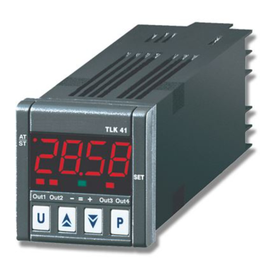
1 – INSTRUMENT DESCRIPTION 1.1 – GENERAL DESCRIPTION TLK 41 is a “single loop” digital microprocessor based controller, with ON/OFF, Neutral Zone ON/OFF, PID single action, PID double action (direct and inverse) control and with AUTOTUNING FAST function, SELFTUNING function and automatic calculation of the FUZZY OVERSHOOT CONTROL parameter for PID control. - Page 3 11 - Led – Shift index: It indicates that the process value is lower than as programmed on par. “AdE”. 12 - Led = Shift index: It indicates that the process value is within the range [SP+AdE ... SP-AdE] 13 - Led + Shift index: It indicates that the process value is higher than as programmed on par. “AdE”.
- Page 4 2 - PROGRAMMING 2.1 – FAST PROGRAMMING OF THE SET POINT This procedure permits to rapidly program the active Set Point and possibly the alarm thresholds (see par 2.3) Push key “P”, then release it and the display will visualise “SP n” (where n is the number of the Set Point active on that moment) alternatively to the programmed value.
-
Page 5: Parameters Programming Levels
To enter into the menu “OPEr” select then the option “OPEr” and push key “P”. Now, the display will show the code identifying the first group of parameters (“ SP “) and with keys “UP” and “DOWN” will be possible to select the parameters group to be modified. Once the desired parameters group has been selected, push key “P”... -
Page 6: Control State
This parameter can be programmed as : =SE: The active Set Point is modifiable while the alarm thresholds are not modifiable =AE :The active Set Point is not modifiable while the alarm thresholds are modifiable =SAE: Whether the active Set Point or the alarm thresholds are modifiable =SAnE: Whether the active Set Point or the alarm thresholds are not modifiable 2.4 –... - Page 7 2.5 – ACTIVE SET POINT SELECTION The instrument permits to pre-program up to 4 different Set point (“SP1”, “SP2”, “SP3”, “SP4”) and then to select which one has to be active. The maximum number of Set point is determined by the par. "nSP" located in the parameters group “ SP “.
-
Page 8: Use Allowed
3 – INSTALLATION AND USE WARNING 3.1 – USE ALLOWED The instrument has been projected and manufactured as measuring and control device to be used according to EN61010-1 approval. The use of the instrument for applications not expressly allowed by the above mentioned rule has to adopt all the necessary protective measures. -
Page 9: Measuring And Visualization
4 - FUNCTIONING 4.1 – MEASURING AND VISUALIZATION All the parameters referred to the measuring are contained into the group “ InP”. Using par. “HCFG” it’s possible to select the input signal type which may come : from a thermocouple (tc), a thermoresistance or a thermistor (rtd), from a transducer with normalised analogue signal in current (I) or tension (UoLt) or furthermore from a signal coming from the communication serial line of the instrument (SEr). -
Page 10: Output Configuration
where: DV = visualised value MV= measured value Example 1: It’s required that the instrument visualises the value effectively measured at 20° but, at 200°, it has to visualise a value lower than 10° (190°). Therefore : M1=20 ; D1=20 ; M2=200 ; D2=190 “rot”... - Page 11 Vice versa, in case of direct action or cooling ("Func”=CooL), ), it deactivates the output, when the process value reaches [SP - HSEt] in case of symmetrical hysteresis, or [SP] in case of asymmetrical hysteresis and it activates it again when the process value goes above value [SP + HSEt].
- Page 12 4.4 – NEUTRAL ZONE ON/OFF CONTROLLER (1rEG - 2rEG) All the parameters referred to the Neutral Zone ON/OFF control are contained into the group “ rEG”. This type of control is obtainable when 2 outputs are programmed respectively as 1rEG and 2rEG and the par. “Cont” = nr . The Neutral Zone control is used to control plants where there is an element which causes a positive increment (ex.
- Page 13 1: Value “FuOC” OK 2: Value “FuOC” too high 3: Value “FuOC” too low 4.5 – DOUBLE ACTION PID CONTROLLER (1rEG - 2rEG) All the parameters referred to the PID control are contained into the group “ rEG”. The Double Action PID control is used to control plants where there is an element which causes a positive increment (ex. Heating) and an element which causes a negative increment (ex.
- Page 14 To activate the AUTOTUNING function do proceed as follows : 1) Program and activate the desired Set Point. 2) Program par. "Cont" =Pid. 3) Program par. "Func" depending on the process to be controlled through output 1rEG. 4) Program an output as 2rEG if the instrument control a plant with double action 5) Program par.
- Page 15 4.8 – REACHING OF THE SET POINT WITH CONTROLLED SPEED AND AUTOMATIC COMMUTATION BETWEEN TWO SET POINT (RISE RAMP, FALL RAMP AND DWELL TIME) All the parameters referred to the ramps functioning are contained into the group “ rEG”. It's possible to reach the set point in a predetermined time (in any case longer than the time the plant would naturally need). This could be useful in those processes (heating or chemical treatments, etc.) on which the set point has to be reached gradually, in predetermined times.
-
Page 16: Soft-Start Function
4.9 - SOFT-START FUNCTION All the parameters referred to the Soft -Start functioning are contained into the group “ rEG”. The Soft-Start function is only working with PID control and allows the limiting of the control power when the instrument is switched on, for a programmable time. - Page 17 "ALnt" – ALARM TYPE : It's possible to have 6 different behaviours of the alarm output. LOAb = ABSOLUTE LOW ALARM: The alarm is activated when the process value goes under the alarm set on parameter "ALn". HIAb = ABSOLUTE HIGH ALARM: The alarm is activated when the process value goes higher than alarm set on parameter "ALn".
- Page 18 "Abn" – ALARM CONFIGURATION: The parameter can assume a value between 0 and 15. The number to be set, which will correspond to the desired functioning, is obtained adding the values reported in the following descriptions : ALARM BEHAVIOUR AT THE SWITCH ON: It’s possible to have 2 different behaviours of the alarm output, depending on the value added to par.
- Page 19 4.9.2 – ALARMS HYSTERESIS The alarm functioning is depending on the alarm hysteresis (par. "HALn"), which works in asymmetric way. In case of low alarm, the alarm will be activated when the process value goes under the alarm threshold value and will be deactivated when it goes higher than the alarm threshold + "HALn"...
- Page 20 Note : The HB current measure is valid if the output 1rEG is activated (or deactivated) for 264 ms. at least. This means that, if the cycle time (“tcr1”) is = 1 sec, the HB alarm is able to intervene only when the output power is higher than 26,4%.
- Page 21 4.14 - RS 485 SERIAL INTERFACE The instrument can be equipped with a RS 485 serial communication interface, by means of which it's possible to connect the regulator with a net on which are connected other instruments (regulators or PLC) all depending typically on a personal computer used as plant supervisor.
-
Page 22: Programmable Parameters
5 – PROGRAMMABLE PARAMETERS Here following are described all the parameters available on the instrument. Some of them could be not present or because they are depending on the type of instrument or because they are automatically disabled as unnecessary. 5.1 –... - Page 23 Group “AL1” (parameters relative to alarm AL1) Par. Description Range Def. Note 24 OAL1 Output where alarm AL1 is addressed Out1 / Out2 Out3 / Out4 Out2 25 AL1t Alarm AL1 type LoAb / HiAb LHAb / LodE HidE / LHdE LOAb Ab1 Alarm AL1 functioning 0 ÷...
- Page 24 Group “rEG” (parameters relative to the control) Par. Description Range Def. Note 58 Cont Control type Pid / On.FA On.FS / nr 59 Func Functionin mode output 1rEg HEAt / CooL HEAt 60 HSEt ON/OFF control Hysteresis -1999 ÷ 9999 61 Auto Autotuning Fast enable OFF / 1 / 2 / 3 62 SELF Selftuning enable...
-
Page 25: Parameters Description
5.2 – PARAMETERS DESCRIPTION GROUP “ SP” (PARAMETERS RELATIVE TO THE SET POINT): They allow the control Set programming and the Set functioning modalities. nSP – NUMBER OF THE PROGRAMMABLE SET POINT: It permits to define the number of the Set Point which are desired to be programmed and stored (from 1 to 4). - Page 26 GROUP “ Out” (PARAMETERS RELATIVE TO THE OUTPUTS): They permit to program the outputs functioning. O1F – FUNCTIONING OF OUTPUT OUT 1: It defines the functioning of output OUT 1 as: control output 1 (1.rEG), control output 2 (2.rEG), alarm output as normally open (ALno), output alarm normally closed (ALnc), output not used (OFF). O2F - FUNCTIONING OF OUTPUT OUT 2: Similar to “O1F”...
- Page 27 AL2H - HIGH THRESHOLD BAND ALARM AL2 : Similar to “AL1H” but referred to alarm AL2. HAL2 - ALARM AL2 HYSTERESIS: Similar to “HAL1” but referred to alarm AL2. AL2d - ACTIVATION DELAY OF ALARM AL2: Similar to “AL1d” but referred to alarm AL2. AL2i - ALARM AL2 ACTIVATION IN CASE OF MEASURING ERROR: Similar to “AL1i”...
- Page 28 GROUP “ AL3” (PARAMETERS RELATIVE TO ALARM AL3): They permit to program the functioning of the process alarm AL3. OAL3 - OUTPUT WHERE ALARM AL3 IS ADDRESSED: It defines on which output the alarm AL3 has to be addressed. AL3t - ALARM AL3 TYPE: Similar to “AL1t” but referred to alarm AL3. Ab3 - ALARM AL3 FUNCTIONING: Similar to “Ab1t”...
- Page 29 GROUP “ rEG” (PARAMETERS RELATIVE TO THE CONTROL): It contains the parameters relative to the control functioning. Cont – CONTROL TYPE: It permits to select one of the possible control mode offered by the instrument : PID (Pid), ON/OFF with asymmetrical hysteresis (On.FA), ON/OFF with symmetrical hysteresis (On.FS), Neutral Zone ON/OFF (nr). Func –...
- Page 30 If instead par. “St.P” = OFF and on par. “SSt” is programmed a value, at the switch on, the power calculated by the PID controller is divided for the time “SSt”, with the meaning to calculate a ramp. The output power starts from 0 and is progressively increased, basing on the calculated ramp, up to the reaching of time “SSt”...
- Page 31 GROUP “ PAn” (PARAMETERS RELATIVE TO THE USER INTERFACE) : It contains the parameters relative to the key U and display functioning. Usrb – FUNCTIONING OF KEY U : It permits to decide which function is associated to key U. The possible selection are : = noF : no function = tunE : Pushing the key for 1 sec.
-
Page 32: Error Signalling
6 - PROBLEMS, MAINTENANCE AND GUARANTEE 6.1 – ERROR SIGNALLING: Error Reason Action - - - - Probe interrupted Verify the correct connection between probe and instrument and then verify the correct functioning of the probe uuuu The measured variable is under the probe’s limits (underrange) oooo The measured variable is higher than... -
Page 33: Technical Data
7 – TECHNICAL DATA 7.1 – ELECTRICAL FEATURES Power supply: 18...30 VAC/VDC, 90... 240 VAC +/- 10% Frequency AC: 50/60 Hz Power consumption: 8 VA approx. Input/s: 1 input for temperature probes: tc J,K,S ; RTD Pt 100 IEC; PTC KTY 81-121 (990 Ω @ 25 °C); NTC 103AT-2 (10KΩ @ 25 °C) or mV signals 0...50 mV, 0...60 mV, 12 ...60 mV or normalized signals 0/4...20 mA, 0/1...5 V , 0/2...10 V. -
Page 34: Functional Features
7.4 – FUNCTIONAL FEATURES Control: ON/OFF, single and double action PID Measurement range: according to the used probe (see range table) Display resolution: according to the probe used 1/0,1/0,01/0,001 Overall accuracy: +/- 0,15 % fs Sampling rate: 130 ms. Serial Interface : RS485 optoisolated Communication protocol: MODBUS RTU (JBUS) Baud rate: Programmable from 1200 ... - Page 35 2 ... 10 V “HCFG” = UoLt “SEnS” = 2.10 7.6 – INSTRUMENT ORDERING CODE TLK 41 a b c d e f g ii a : POWER SUPPLY L = 18 ... 30 VAC/VDC H = 90 ... 240 VAC...
Need help?
Do you have a question about the TLK 41 and is the answer not in the manual?
Questions and answers