
Subscribe to Our Youtube Channel
Related Manuals for THORLABS PWA090


Summary of Contents for THORLABS PWA090
- Page 1 PWA090 Electronic, Self-levelling, Benchtop Isolation System User Guide Original Instructions HA0260T...
-
Page 2: Table Of Contents
4.6 Save Settings ..................23 4.7 Return ....................23 Appendices Appendix A Connector Pinout Detail ............24 Appendix A Load Position and Stability............25 Appendix B Preventive Maintenance ............26 Appendix C Specifications................27 Appendix D Regulatory ................28 Appendix E Thorlabs Worldwide Contacts ..........29 Page 0... -
Page 3: Chaper 1 Overview
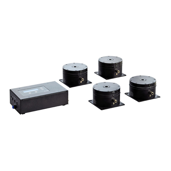
Chapter 1 Overview Chapter 1 Overview 1.1 Introduction The PWA090 electronic, self-levelling, vibration isolation system, provides a portable, lightweight, low-profile vibration-control solution for sensitive benchtop equipment and experiments. The system comprises a set of four pneumatic isolators (which must be connected to a compressed air supply) and an electronic control box. -
Page 4: Chaper 2 Safety
Chapter 2 Safety 2.1 Safety Information For the continuing safety of the operators of this equipment, and the protection of the equipment itself, the operator should take note of the Warnings, Cautions and Notes throughout this handbook and, where visible, on the product itself. The following safety symbols may be used throughout the handbook and on the equipment itself. -
Page 5: Chaper 3 Installation
Chapter 3 Installation Chapter 3 Installation 3.1 Installation 3.1.1 Siting The system is designed to be mounted on a benchtop or similar surface. The isolators can be used free standing to provide a temporary isolation solution. For more permenant applications, the isolators can be bolted to an imperial or metric tapped work surface - see Section 3.1.3. - Page 6 Electronic, Self-levelling, Benchtop Isolation System 4” (100 mm) 4” (100 mm) 4” (100 mm) 4” (100 mm) Fig. 3.1 Positioning the isolators 2) The base plate of each leg is fitted with four slotted holes to enable secure fixing to the work surface. The orientation of the legs, when mounting to imperial and metric tapped surfaces is shown below.
-
Page 7: Electrical Connections
Chapter 3 Installation 3.1.4 Electrical Connections 1) Using the leads supplied, connect the Feedback terminals on the master legs, to the corresponding LEG 1, LEG 2 and LEG 3 FEEDBACK INPUT connections on the control box - see Fig. 3.3 and Fig. 3.4. The slave leg has no feedback terminal. 2) Connect the control box to the power supply shipped with the unit but DO NOT apply power. -
Page 8: Pneumatic Connections
Electronic, Self-levelling, Benchtop Isolation System 3.1.5 Pneumatic Connections 1) Using the 6mm outside diameter nylon tubing, connect the pneumatic connectors on each master leg, to the LEG 1, LEG 2 and LEG 3 PNEUMATIC OUTPUT connections on the control box - see Fig. 3.6 and Fig. 3.7. Note that the slave leg is driven by a master leg - see item (2). - Page 9 Chapter 3 Installation Fig. 3.7 Pneumatic connections 2) Using the 6mm outside diameter nylon tubing and the T-piece supplied, connect the slave leg to one of the master legs as shown below. To LEG connector on Control Box Fig. 3.8 Slave Leg connections 3) Ensure that the air supply is turned OFF, then connect the AIR IN terminal on the Control Box (see Fig.
-
Page 10: Fitting/Removing The Breadboard
Electronic, Self-levelling, Benchtop Isolation System 3.2 Fitting/Removing The breadboard A Installation 1) Perform the installation procedures as detailed in Section 3.1. 2) Fit the lifting handles supplied to the breadboard as shown in below. Fig. 3.9 Fitting the breadboard Warning During item (3): Breadboards should be manipulated using the lifting handles supplied. -
Page 11: Switching On
Chapter 3 Installation 3) Observing the warnings listed above, lift the breadboard into position - see Fig. 3.9. 4) Populate the breadboard. Wherever possible, the load should be distributed evenly. Unevens or tall loads may adversely effect the settling time and stability. See Appendix Bfor more information Caution During item (4), the total load including the breadboard must not exceed 210kg... - Page 12 Table 3.1 Typical pressure versus weight Note If the weight of the load is unknown, consult www.thorlabs.com to find the weight of the breadboard (weights are listed by part number and by size), then estimate the weight of the experiment. Further tuning can be performed once the system is ‘floated’.
-
Page 13: Chaper 4 Set Up
Chapter 4 Set Up Chapter 4 Set Up 4.1 Front Panel Controls and Indicators Active Levelling Controller MENU ENTER Fig. 4.1 Control Panel Digital Display – 2-line, 16-digit liquid crystal display. In normal operation, the top line (I) shows the nominal position of each leg in 10 µm steps, (-250 to 250 which relates to ±2.5 mm), and the bottom line (O) shows the output voltage applied to each valve (in encoder counts, 0 to 999 which relates to 0 to 12 V). -
Page 14: Set Up Menu
Electronic, Self-levelling, Benchtop Isolation System 4.2.1 Set Up Menu Press the MENU button to enter the Set Up Menu. MENU Press the Up and Down keys to move between levels. This level allows preset PID parameters for a specific load Weight Selection and pressure to be applied - see Section 4.3. -
Page 15: Initial Set Up
Chapter 4 Set Up 4.3 Initial Set Up Before the system can be used, it must be configured to operate with the specific load and pressure with which it is being used. Perform the installation procedure detailed at Chapter 3 then proceed as follows: Ensure that the air pressure and system power are switched ON (see Section 3.2.1.). -
Page 16: Weight/Pressure (Default Pid) Selection
Electronic, Self-levelling, Benchtop Isolation System 4.3.2 Weight/Pressure (Default PID) Selection ...Continued from previous page Before the system can be ‘floated’, the PID parameters must be set for the associated load and air pressure. These are applied automatically when the weight is selected. Press the UP/Down keys to scroll to the Weight Selection panel, which contains default PID values Weight Selection... -
Page 17: Switching On Active Leveling
Chapter 4 Set Up 4.3.3 Switching ON Active Leveling ...Continued from previous page Before the system can be ‘floated’, the ‘Active Leveling’ system must be switched ON. MENU Press the DOWN key to step through to the Active Active Leveling Leveling panel. -
Page 18: Levelling The System
Electronic, Self-levelling, Benchtop Isolation System 4.4 Levelling the System 4.4.1 Settle Position The Settle Position parameters are the demanded positions of each leg and are used to level the system. On initial set up, these parameters are typically set to ‘0’ which is an arbitrary mid position (it is normal for each leg to have a different ‘0’... -
Page 19: Error Band
Chapter 4 Set Up 4.4.2 Error Band The Error Band setting is provided to improve the repeatability and/or settling time of the system and is defined as the allowable error between the actual and demanded position on a particular leg. A large error band results in a fast settling time whereas a small error band results in improved repeatability When the difference between the actual and demanded position is within the band, the associated LEG LED on the key pad is lit. -
Page 20: Further Tuning And Pid Parameter Adjustment
Electronic, Self-levelling, Benchtop Isolation System Further Tuning and PID Parameter Adjustment The control box contains a number of hall effect sensors which use a position control loop to determine the command output. The purpose of the position loop is to match the actual leg position and the demanded position. - Page 21 Chapter 4 Set Up Press the MENU button to enter the set up level then MENU press the DOWN key to step through to the PID Params panel. PID Parameters ENTER Press ENTER to access the level. A warning screen is displayed to guard against accidental adjustment.
- Page 22 Electronic, Self-levelling, Benchtop Isolation System The present setting for the Intergral term is displayed. Integral ENTER Press the DOWN key to advance to the Derivative term, or press ENTER to set the Integral value. Integral The display flashes to show that editing is active. Use the UP and DOWN keys to set the desired value.
- Page 23 Chapter 4 Set Up The present setting for the Derivative term is displayed. Derivative ENTER Press the DOWN key to advance to the Proportional term, or press ENTER to set the Derivative value. Derivative The display flashes to show that editing is active. Use the UP and DOWN keys to set the desired value.
- Page 24 Electronic, Self-levelling, Benchtop Isolation System PID Settings Summary System overshoots the intended position - reduce Integral and increase Derivative and Proportional terms. System doesn't attain final position - increase the Integral and Proportional terms. System is unstable - reduce Proportional and Integral, increase Derivative. System sounds noisy - reduce Derivative.
-
Page 25: Save Settings
Chapter 4 Set Up 4.6 Save Settings Once the set up procedure has been performed, the settings can be saved to memory so they will be available next time the system is powered up. The following settings are saved: Units, Weights/Pressure, Active Levelling ON/OFF, Settle Position, Error Band, PID settings. -
Page 26: Appendix A Connector Pinout Detail
Appendix A Connector Pinout Detail A.1 Controller FEEDBACK Connectors This 6-pin mini DIN connector provides connection to the feedback signal from the hall effect sensors in each leg. The pin functions are detailed in Fig. A.1. Description Leg Position Ground Ground Not Connected Ground... -
Page 27: Appendix A Load Position And Stability
Chapter 4 Set Up Appendix B Load Positioning and Stability B.1 Maximising System Stability B.1.1 System Stability Zone The location and height of a load placed on a work surface can dramatically affect the stability and function of the isolation system. To ensure optimum effectiveness of the isolators, it is important to avoid any instability due to the system centre of mass being misplaced. -
Page 28: Appendix B Preventive Maintenance
The equipment contains no user servicable parts. There is a risk of electrical shock if the equipment is operated with the covers removed. Only personnel authorized by Thorlabs Ltd and trained in the maintenance of this equipment should remove its covers or attempt any repairs or adjustments. Maintenance is limited to testing and cleaning as described in the following sections. -
Page 29: Appendix C Specifications
Chapter 4 Set Up Appendix D Specifications Parameter Value <1.7 Hz Vertical Resonant Frequency 7.0 Hz Horizontal Resonant Frequency 14.22 dB Vertical Transmissibility at Resonance -27 dB (95.66%) Vertical Transmissibility at 10 Hz 16.27 dB Horizontal Transmissibility at Resonance -4.5 dB Horizontal Transmissibility at 10 Hz Maximum Load Capacity (set of four) 462 lb (210 kg) -
Page 30: Appendix D Regulatory
Appendix E Regulatory E.1 Declarations Of Conformity E.1.1 For Customers in Europe This equipment has been tested and found to comply with the EC Directives 89/336/EEC ‘EMC Directive’ and 73/23/EEC ‘Low Voltage Directive’ as amended by 93/68/EEC. Compliance was demonstrated by conformance to the following specifications which have been listed in the Official Journal of the European Communities: Safety EN61010: 2001 Installation Category II, Polution Degree II. -
Page 31: Appendix E Thorlabs Worldwide Contacts
Waste treatment is your own responsibility. "End of life" units must be returned to Thorlabs or handed to a company specializing in waste recovery. Do not dispose of the unit in a litter bin or at a public waste disposal site. - Page 32 www.thorlabs.com...
Need help?
Do you have a question about the PWA090 and is the answer not in the manual?
Questions and answers