Table of Contents
Advertisement
Quick Links
Best practices for the HP Modular Cooling System
best practice
Abstract.............................................................................................................................................. 1
HP MCS Product overview .................................................................................................................... 1
Product components ............................................................................................................................. 3
MCS Specifications.............................................................................................................................. 3
Additional Resources ........................................................................................................................ 4
Certification and regulatory compliance ................................................................................................. 4
Integration services and software........................................................................................................... 5
HP UPS Sizing Tool .......................................................................................................................... 5
Additional resources ..................................................................................................................... 5
MCS documentation CD ................................................................................................................... 5
HP Modular Cooling System Management Module .............................................................................. 5
MCS deployment considerations............................................................................................................ 5
Levels of HP MCS security ................................................................................................................. 5
HP MCS Front Doors..................................................................................................................... 6
HP MCS Rear Doors ..................................................................................................................... 6
HP Side Panel Kit ......................................................................................................................... 6
Stabilization for seismic activity ......................................................................................................... 6
Space and cable management requirements ....................................................................................... 6
Extension kits ............................................................................................................................... 6
Cable management kits................................................................................................................. 7
Thermal requirements ....................................................................................................................... 7
Automatic door opening mechanism .................................................................................................. 7
Insulation Considerations .................................................................................................................. 7
Additional resources......................................................................................................................... 8
HP MCS assembly guidelines ................................................................................................................ 8
Additional resources......................................................................................................................... 8
HP MCS Installation and maintenance precautions .................................................................................. 9
HP MCS side service access .......................................................................................................... 9
Moving an HP MCS on its casters .................................................................................................. 9
Connecting and disconnecting power to hot-pluggable power supplies............................................. 10
Advertisement
Table of Contents

Related Manuals for HP MCS


Summary of Contents for HP MCS
-
Page 1: Table Of Contents
HP MCS assembly guidelines ........................ 8 Additional resources......................... 8 HP MCS Installation and maintenance precautions .................. 9 HP MCS side service access ......................9 Moving an HP MCS on its casters ....................9 Connecting and disconnecting power to hot-pluggable power supplies..........10... - Page 2 Rack-mountable components ......................10 Aligning the HP MCS with HP 10000 Series racks................11 Data Center planning and considerations ..................... 11 Environmental considerations ......................11 Power considerations........................12 Power redundancy ........................12 Non-redundant........................... 12 High line voltage versus low line voltage..................13 Grounding and Earth leakage current ...................
-
Page 3: Abstract
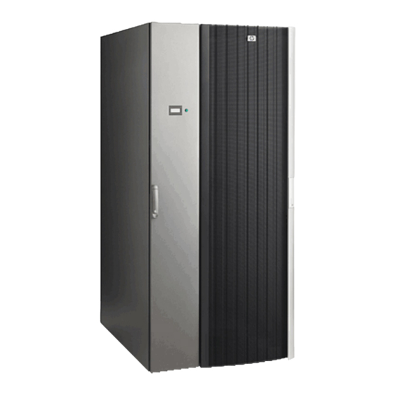
Modular Cooling System (HP MCS) as used with the HP 10000 G2 Series Rack Model 10642 G2. HP MCS Product overview The HP MCS (Figure 1) cools the warm air that is generated by equipment installed in a 10642 G2 rack. The MCS unit is designed for high-density server and blade deployments. The horizontal air flow of the MCS unit distributes cooled air uniformly throughout the complete height of the enclosure (i.e.,... - Page 4 The MCS unit cools and circulates air through the 10642 G2 rack as outlined in the following steps (Figure 2): The rack-mounted components in the 10642 G2 rack receive cooled air from the MCS unit. The cooled air provides cooling for the components.
-
Page 5: Product Components
The Automatic Door Release Kit Release Kit is designed to swing the MCS front and rear doors open in the case of a sudden increase in the temperature inside the MCS. The open doors will allow the IT equipment to cool using the air from the datacenter. -
Page 6: Additional Resources
Table 4 provides dimensions and weights of a packed and unpacked MCS unit and rack that is not populated with rack-mounted components (i.e., an empty rack). Table 4. HP MCS and Server Cabinet Dimensions and Weights Detail Unpackaged rack with pre-installed MCS unit... -
Page 7: Integration Services And Software
Levels of HP MCS security Either of the following conditions may be necessary for compliance with certain safety certifications: • The HP MCS must be located in a restricted access area that is only accessible to trained personnel. -Or- • The HP MCS must be configured with lockable hardware. -
Page 8: Hp Mcs Front Doors
An equipment integrator will need to determine the requirements for which, if any, ballast and stabilizer kits are required. If the HP MCS is bolted to the floor or to an adjacent HP MCS that has sufficient combined weight, additional stabilization products may not be required. -
Page 9: Cable Management Kits
Fiber cables must not violate their minimum bend radius – no exceptions. • When securing cables inside the HP MCS, the bundle should be dressed in such a way as to avoid interference with installed components or HP MCS side panels or rails. -
Page 10: Additional Resources
• For information on the HP Modular Cooling System refer to the HP Modular Cooling System Site Preparation Guide and white papers available at http://h20000.www2.hp.com/bizsupport/TechSupport/Home.jsp?lang=en&cc=us&prodTypeId=3 29290&prodSeriesId=1155256. • For a list of the HP MCS documentation including the HP Modular Cooling System Site Preparation Guide, go to http://h20000.www2.hp.com/bizsupport/TechSupport/DocumentIndex.jsp?contentType=SupportManual&lan g=en&cc=us&docIndexId=179111&taskId=101&prodTypeId=329290&prodSeriesId=1155256 HP MCS assembly guidelines Table 5 lists guidelines to follow when physically placing components in an HP MCS. -
Page 11: Hp Mcs Installation And Maintenance Precautions
Therefore, it is recommended and also easier to move the HP MCS with the back as the leading edge. Roll the HP MCS with fixed casters first. When rolling the HP MCS, make sure to push firmly on the doorframe and not the door mesh. -
Page 12: Connecting And Disconnecting Power To Hot-Pluggable Power Supplies
• Install the power supply before connecting the power cord to the power supply. • Do not overload the AC supply branch circuit that provides power to the HP MCS. The total HP MCS load should not exceed 80 percent of the branch circuit rating. -
Page 13: Aligning The Hp Mcs With Hp 10000 Series Racks
Aligning the HP MCS with HP 10000 Series racks The HP MCS can be installed next to an existing or new row of HP 10000 Series racks. Based on the facility design requirements, the cabinets can be arranged in a flus-front (Figure 5) or flush-rear (Figure 6) configuration. -
Page 14: Power Considerations
To provide proper front-to-back air flow, any open "U" space in the front of the HP MCS must be covered with a HP 10000 Series Universal Filler Panel. -
Page 15: High Line Voltage Versus Low Line Voltage
• Greater power capacity in a single HP MCS. For the same size circuit, almost twice the power can be delivered to an HP MCS at high line versus low line. For example, a 115V 30A branch circuit can deliver 3450VA to an HP MCS, while a 230V 30A branch can deliver 6900 VA to an HP MCS. -
Page 16: Equipment Clearance And Floor Loading
Equipment clearance and floor loading A minimum clearance of 48 inches in front of a configured HP MCS and 30 inches to the rear of a configured rack is recommended. All buildings and raised computer room floors are engineered to provide a specific floor loading. -
Page 17: Qualified Shipping
Qualified shipping The HP MCS ships pre-installed to a 10000 G2 Series rack. The MCS is CTO-capable for up to 2000 Lbs and ships standard with a shock pallet. The MCS can be used to factory-integrate IT equipment at Factory Express or other configuration services. -
Page 18: Hp Mcs Shipping Specifications
(1778 mm) (621.4 kg) (908 kg) HP MCS packing materials Figure 10 shows the typical packaging material shipped with the empty HP MCS upon arriving at the customer configuration site. Figure 10. HP MCS on shipping pallet Items shown: Items not shown: 1. -
Page 19: Site Preparation For Receiving The Hp Mcs
• Will the HP MCS be removed from the pallet at a location other than the final installation location? • Is movement across rough surfaces likely? •... -
Page 20: Airfreight
Airfreight Because the HP MCS cannot be safely tipped or placed on its side during transit or storage, air cargo doors must have height sufficient for the HP MCS to be loaded and removed without tipping. Consult your freight forwarder for available aircraft configurations that satisfy your particular HP MCS height. - Page 21 If the HP MCS had been built out for CTO and then put on a plane, the documents would come from the factory or the group building out the HP MCS.
-
Page 22: Mode Of Receiving And Delivery
Formica are recommended to minimize the vibration induced into the HP MCS. • Be aware that the HP MCS is 85.5 in. (2170 mm) high on the skid and exceeds standard 7-foot doorways so the HP MCS will have to be de-palletized for passage through the standard 7-foot doorframe. -
Page 23: Dismounting The Hp Mcs From The Shipping Pallet
Dismounting the HP MCS from the shipping pallet To dismount the HP MCS, reverse the process for assembling the shock pallet. Figure 12 illustrates the dismounting process for the HP MCS. HP MCS Figure 12. dismounting steps Installation service In the United States, HP can arrange to have your HP MCS installed by qualified service providers. -
Page 24: Appendix A: Glossary
A dedicated electrical circuit between a source and distribution point. Dynamic loading capacity A dynamic environment is one where the HP MCS is shipped on a shock pallet with equipment installed or rolling HP MCSs with equipment installed to new locations within the data center. -
Page 25: Appendix B: Torque Values
Appendix b: torque values Table 9 provides torque values for specific components. Table 9. Torque values (specific) Component Torque (in-lb) Torque (N-m) All M6 rack hardware 20 in-lb 2.26 N-m Pallet bracket hold-down bolts 150 in-lb 16.95 N-m All Phillips-head screws 20 in-lb 2.26 N-m All M5-M6 slotted-torx head screws... -
Page 26: For More Information
HP products and services are set forth in the express warranty statements accompanying such products and services. Nothing herein should be construed as constituting an additional warranty. HP shall not be liable for technical or editorial errors or omissions contained herein.
Need help?
Do you have a question about the MCS and is the answer not in the manual?
Questions and answers