Table of Contents
Advertisement
Quick Links
Installation and operating instructions
ELECTRIC FRYERS FOR
PROFESSIONAL USE
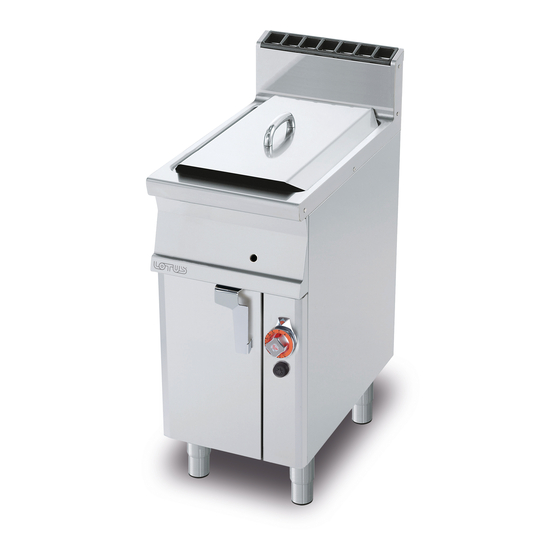
F10D-64ETX F2/10D-66ETX
F18D-64ETX F2/8D-64ETX
Model LIBR.ISTR.FDX POT
Code 563022401
Review 1
Edition date 22/04/2020
Language English
LOTUS S.p.A.
Via Calmaor, 46
31020 San Vendemiano
+39 0438 778020
+39 0438 778277
Translation of the original instructions
Advertisement
Table of Contents

Subscribe to Our Youtube Channel
Related Manuals for Lotus F10D-64ETX


Summary of Contents for Lotus F10D-64ETX
- Page 1 Installation and operating instructions ELECTRIC FRYERS FOR PROFESSIONAL USE F10D-64ETX F2/10D-66ETX F18D-64ETX F2/8D-64ETX Model LIBR.ISTR.FDX POT Code 563022401 Review 1 Edition date 22/04/2020 Language English LOTUS S.p.A. Via Calmaor, 46 31020 San Vendemiano +39 0438 778020 +39 0438 778277 Translation of the original instructions...
-
Page 2: Table Of Contents
Contents Contents INTRODUCTION ......................... Installation drawing ........................Components..........................GENERAL INFORMATION......................Declaration of compliance......................User information, RAEE Directive on waste electrical and electronic equipment ......Technical data table ........................INSTALLATION........................... Delivery checks ..........................Removing the packaging ......................Mechanical installation ......................... Electrical/gas connections ......................INSTRUCTIONS FOR USE...................... -
Page 3: Introduction
INTRODUCTION 1 INTRODUCTION Installation drawing FIG. 1 F10D-64ET , F2/10D-66ET Translation of the original instructions... - Page 4 INTRODUCTION MODEL F10D-64ETX 400mm 200mm 87,5mm F2/10D-66ETX 600mm 150mm 37,5mm B Electrical connection Translation of the original instructions...
- Page 5 INTRODUCTION FIG. 2 F18D-64ET B Electrical connection Translation of the original instructions...
- Page 6 INTRODUCTION FIG. 3 F2/8D-64ET B Electrical connection Translation of the original instructions...
-
Page 7: Components
INTRODUCTION Components FIG. B (ROTARY RESISTANCE) 1 O-rings 2 Rotary heating element Caution These fryers are equipped with an acoustic-visual alarm, which is activated when the safety thermostat trips (oil overtemperature). To interrupt the alarm, turn the control knob to zero (but the system remains operational until the problem that caused the intervention is resolved) ... - Page 8 INTRODUCTION WIRING DIAGRAM (C) 1 Cicada 2 Switch 3 Microswitch 4 Power supply terminal board 5 Heating element 6 Resistance voltage drop 7 White indicator light 8 Red indicator light 9 Green indicator light 10 Contactor 11 Thermostat 12 Safety thermostat Translation of the original instructions...
- Page 9 INTRODUCTION Electrical technical data table MODEL WIRING DIAGRAMS F10D-64ETX F18D-64ETX F2/10D-66ETX C + C F2/8D-64ETX C + C PREDISPOSITION 440V~3 Translation of the original instructions...
-
Page 10: General Information
GENERAL INFORMATION 2 GENERAL INFORMATION Declaration of compliance The manufacturer declares that the appliances comply with the requirements of the regulation GAR 2016/426 for the gas part and directive 2014/30/EU,2014/35/EU for the electrical part. Installation must be performed in compliance with current regulations, especially with regard to ventilation of the premises and the exhaust gas evacuation system. -
Page 11: User Information, Raee Directive On Waste Electrical And Electronic Equipment
Technical data table Electrical technical data table FDX MAXIMUM POWER Silicon POWER MODEL POWER SUPPLY MAXIMUM INPUT (A) (kW) SUPPLY CABLE F10D-64ETX 400V~3 50/60 Hz 7,15 10,36 4 x 1,5 mm² F10D-64ETX 440V~3 60 Hz 7,15 9,38 4 x 1,5 mm²... -
Page 12: Installation
INSTALLATION 3 INSTALLATION Delivery checks On delivery, it is important to check the following: · External conditions of the packaging · The general status of the equipment · The conformity of the model with the information in the technical data plate and the instruction manual ·... - Page 13 INSTALLATION Note The ID plate is located in the compartment inside the door for appliances with compartments, or on the left side for appliances with an oven or a top. A second plate with the model and serial number is located inside the dashboard and a third is included with the certificate of conformity.
- Page 14 INSTALLATION Note The connection cable must have the following characteristics: it must be silicone type (to withstand temperatures of 180 °C), and must have an appropriate cross-section for the power of the appliance (see technical data table). EQUIPOTENTIAL ...
-
Page 15: Instructions For Use
INSTRUCTIONS FOR USE 4 INSTRUCTIONS FOR USE General information This appliance must only be used for its expressly intended purpose for cooking or heating food. Any other use is considered improper. The appliance is also intended for industrial use and must only be used by personnel trained for use and aware of the risks that the hot element entails. -
Page 16: Emptying The Tank
INSTRUCTIONS FOR USE If using the fryer with products other than oil (lard, for example) that have considerable thermal inertia, it is necessary to set the thermostat to a low value (e.g. 110°C) during the first cycle (not starting cold). The thermostat can be set to the maximum only after the entire mass has melted ... -
Page 17: Maintenance
MAINTENANCE 5 MAINTENANCE Routine When using the appliance over time, it is essential to perform regular maintenance to ensure safe operation. We therefore recommend stipulating a service contract. Caution Maintenance must only be performed by specialist personnel in compliance with current ... -
Page 18: Spare Parts
MAINTENANCE Spare parts It is possible to replace parts such as the valve, the piezoelectric or the ignition control unit (depending on the type of appliance) or the gas pipes easily and quickly. To replace such parts, proceed as follows: ... -
Page 19: Cleaning
CLEANING 6 CLEANING Routine cleaning Caution The use of flammable fluids to clean the appliance is forbidden To ensure hygiene and the durability of the appliance, perform external cleaning on a regular basis, taking care not to damage the cables and the electrical connections. Before starting cleaning, disconnect the appliance from the power supply.
Need help?
Do you have a question about the F10D-64ETX and is the answer not in the manual?
Questions and answers