
Related Manuals for YSI 650 MDS


Summary of Contents for YSI 650 MDS
- Page 1 Environmental P u r e D a t a f o r H e a l t h y P l a n e t . ™ YSI 650 MDS Multiparameter Display System Operations Manual...
- Page 2 YSI Incorporated 650 MDS...
-
Page 3: Table Of Contents
9.4 LOGGING BAROMETER READINGS SECTION 10 UPGRADING 650 SOFTWARE SECTION 11 TROUBLESHOOTING SECTION 12 FERRITE BEAD INSTALLATION SECTION 13 650 SAFETY CONSIDERATIONS SECTION 14 WARRANTY AND SERVICE INFORMATION SECTION 15 REQUIRED NOTICE SECTION 16 650 MDS SPECIFICATIONS YSI Incorporated 650 MDS... - Page 4 SAFETY AND EMC CONSIDERATIONS 650 MDS Before using the 650 MDS, the user should carefully read the caution messages listed below and should review Section 13 of this manual on Safety Considerations. CAUTION: The YSI 660 can be used with an optional 6117 rechargeable battery pack that contains Nickel Metal Hydride Batteries which if misused or not disposed of properly can cause injury.
-
Page 5: Section 1 Introduction
SECTION 2 GETTING STARTED This section is designed to quickly familiarize you with the hardware and software components of the YSI 650 and its accessories. By the end of Section 2 you will have... Unpacked the YSI 650 and confirmed that all components are present Become familiar with the general features and setup configurations of your YSI 650. -
Page 6: Unpacking
If any parts are damaged or missing, contact your YSI representative immediately. If you do not know which YSI dealer you obtained your YSI 650 from, refer to Section 14 of this manual for contact information. -
Page 7: 650 Configurations
650, and the management of these data files are described in detail in Sections 5-7 of this manual. 2.3 650 CONFIGURATIONS There are a number of ways that you can configure the YSI 650. Below is a list of possible configurations and corresponding diagrams. - Page 8 • User-supplied GPS unit with DE-9 cable with DE-9 cable • YSI 6-series sonde with integral or field cable 6115 GPS cable Integral or field cable YSI 6-series sonde Figure 3. 650 interfaced to PC for data transfer or software upgrade.
- Page 9 The setup of these configurations is described in detail in subsequent sections of this manual. They are presented here so that your will be able to ascertain if you have all of the parts necessary for your applications. YSI Incorporated 650 MDS...
-
Page 10: 650 Features
Strain Relief Lanyard Note that the YSI 650 keypad consists of 20 keys as shown in the diagram above. There are four function keys, up, down, right and left arrow keys and an alpha/numeric keypad. The top left key that has a green circle and line, , is the ON/OFF key. -
Page 11: Batteries And Charging
2.5 BATTERIES AND CHARGING The YSI 650 can be powered either with 4 alkaline C cells or a rechargeable NiMH battery pack. With the C-cell configuration, the user will be able to power a typical YSI 6-series sonde (active dissolved oxygen and one optical sensor) for approximately 45 hours of continuous operation. - Page 12 Reinstall battery lid and tighten the 4 captive screws securely and evenly using a Phillips or slotted screwdriver. Do not overtighten. 2.5.2 BATTERY INSTALLATION – RECHARGEABLE BATTERY PACK The YSI 6113 rechargeable battery pack is self-contained and is easily installed according to the instructions and diagrams below: •...
- Page 13 Note that YSI provides recharge options for many countries in the selection or the 6116, 6126, and 6127 kits. However, it is possible that the power cord options in these kits will not be correct for some users. In these cases, users should purchase the 6126 or 6127 kit and substitute their local PC type power cord for the power cord shipped with the kit.
-
Page 14: Turning The Instrument On
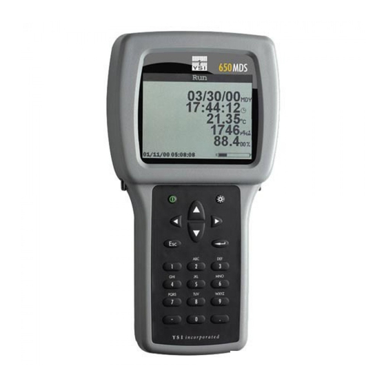
2.6 TURNING THE INSTRUMENT ON Turn the instrument on by pressing and releasing the on/off button on the top left of the instrument keypad. The following screen should be displayed. Main Display Status Bar YSI Incorporated 650 MDS... -
Page 15: Adjusting The Display Contrast
(lightens) the contrast. NOTE: The backlight itself will only be activated if the backlight key is pressed and released. You must hold down the backlight key to adjust the contrast. YSI Incorporated 650 MDS... -
Page 16: Using The 650 Keypad
2.8 USING THE YSI 650 KEYPAD On/Off Backlight Arrows Escape Key Enter Key Alpha/Numeric Keys Minus/Hyphen (-) Key Period (.) Key The 650 keypad allows the user to navigate various sonde and 650 menu selections and to make alpha/numeric entries into both the 650 and sonde software. The arrow keys are used to select various options in the menus;... - Page 17 Use the arrow keys to highlight the System setup selection and press the Enter key. A display similar to the following will appear (Note that the exact format of your displays will depend on the software version): YSI Incorporated 650 MDS...
- Page 18 For example, 2:00 PM must be entered as 14:00. Finally, press the Escape key to return to the System setup menu. Now highlight the Instrument ID selection and press Enter. The following display will appear. YSI Incorporated 650 MDS...
-
Page 19: Connecting To A Sonde
The connection between the sonde and the 650 is made via the mating of MS-8 connectors on the standard YSI field cable and the bottom of the 650 case. To make the connection, hold the 650 in one hand, place the 650 and cable connectors together, and rotate the field cable connector until engagement occurs. - Page 20 To return to the 650 Main menu, press the Escape key. CAUTION: When using the 650 MDS in field applications which are in close proximity to communication towers and heavy industrial equipment, or which involve very low humidity conditions, the user may experience problems with logger function.
-
Page 21: Understanding The Status Bar
2.10.2 GPS Reading. This value will be present only if a user-supplied GPS unit with NMEA 0183 format is connected to the 650 by the optional YSI 6115 cable. The setup of a GPS interface is described in more detail in Section 8 below. Once properly connected to a GPS instrument, the values displayed in the Status Bar are updated in real-time as the system is moved from location to location. -
Page 22: Upgrading Ecowatch For Windows Software
2.11 UPGRADING ECOWATCH FOR WINDOWS SOFTWARE To utilize the full capability of the 650 MDS, you will need to upgrade your version of EcoWatch for Windows from the YSI World Wide Web page (www.ysi.com). Access the YSI Environmental Web Page, select “tech support”... - Page 23 The software version of your 650 is shown in the first line of the System setup menu. As enhancements are introduced to the 650, you will be able to upgrade your 650 from the YSI web page. This item will be used to track those upgrades and will be useful to YSI Customer Service personnel if you have questions about the function of the instrument.
- Page 24 .glp extension (e.g., 00003245.glp) will automatically be generated and stored in 650 memory. Each additional barometer calibration record for will also be stored. See Section 6.3 below for the transfer of this file to a computer for viewing and storage. YSI Incorporated 650 MDS...
-
Page 25: Section 4 Sonde Menu Interface
6-series sonde. Note also that the 650 display has been designed to be very similar to that presented on a monitor when a 6-series sonde is attached to a PC as shown below. ------------------Main----------------- 1-Run 5-System 2-Calibrate 6-Report 3-File 7-Sensor 4-Status 8-Advanced Select option (0 for previous menu): YSI Incorporated 650 MDS... - Page 26 Uploading files from the sonde memory to the 650. Earlier YSI display/loggers, such as the 610 D and 610 DM, had many of these functions as distinct items in the display menu structure – a significant difference from the 650.
-
Page 27: Sonde Menu Examples
4.2 SONDE MENU EXAMPLES To become familiar with the 650 Sonde menu function, YSI recommends that the user connect a sonde to their 650 and proceed through the following two examples of common sonde interface operations. Example 1: Setting up the Report Output – Activation of the Salinity Parameter Highlight the Sonde menu selection in the 650 Main menu and press Enter. - Page 28 650 is equipped with a barometer. When the dissolved oxygen reading is stable, press the Enter key to confirm the calibration as indicated by the message “Calibrated” in the header. In addition, the message in the upper window will change from YSI Incorporated 650 MDS...
-
Page 29: Common Operations Using 650 Sonde Menu Selection
650 memory with the 650 display indicating that an upload is in progress. The uploading of data files from sondes to the 650 is demonstrated in greater detail in Section 7 below. YSI Incorporated 650 MDS... - Page 30 The rules are particularly important with regard to the method of dissolved oxygen calibration – automatic at the Unattended sample interval if Autosleep is Active; manually controlled by the user if Autosleep is inactive. See Section 2 of the 6-series manual for additional information on the Autosleep function. YSI Incorporated 650 MDS...
-
Page 31: Section 5 Logging Data With The 650
September 1999. The two modes of activating the 650 Run display prior to the logging of data to either sonde or 650 memory are shown in schematic fashion in the following drawing: YSI Incorporated 650 MDS... - Page 32 Sonde logging window. While the following sections will show that the logging functions of the 650 have a high degree of flexibility and capability, from a basic point of view, logging with the 650 is simple: YSI Incorporated 650 MDS...
-
Page 33: Logging Data To Sonde Memory
5.2 LOGGING DATA TO SONDE MEMORY 5.2.1 INTRODUCTION All YSI 6-series sondes sold since September 1999 have memory present on their internal PCBs. In addition, all 600XLM, 6920, and 6600 sondes have internal memory, regardless of the date of purchase. Interface of these sondes to a 650 allows the user to easily store data (either a single point or a continuous stream) to the sonde memory. - Page 34 As explained above, the sample interval for logging to sonde memory is set in the Discrete sample menu of the sonde, and thus the user MUST activate the 650 Run display indirectly using the 650 Sonde menu selection as detailed above. YSI Incorporated 650 MDS...
- Page 35 Enter to begin logging data to sonde memory. The message in the sonde logging window changes to Stop logging, indicating that logging has successfully been activated. YSI Incorporated 650 MDS...
- Page 36 With sondes of this type, you will not be able to log data to the sonde – only to the 650 as detailed in the following section. With these no-memory sondes attached to your 650, the Run display will show a blank Sonde logging window as shown below. YSI Incorporated 650 MDS...
-
Page 37: Logging Data To 650 Memory
The factory default sample interval of 1 second will therefore need to be changed to 10 seconds. To set the sample interval, highlight the Logging setup entry in the 650 Main menu and press Enter. YSI Incorporated 650 MDS... - Page 38 The user places the sonde in the water and then highlights the Start logging selection in the 650 logging window (upper left) and presses Enter. The user is then prompted to enter a Filename and Site description for the study as shown below. YSI Incorporated 650 MDS...
- Page 39 “mismatched” with “DO %” from the old setup. The screen thus shows that salinity has been added to the parameter list between the two logging studies and must be removed if the original file is to be appended with further data. YSI Incorporated 650 MDS...
- Page 40 For Multi-site Designations, there will a single File Name with multiple Site Names and Site Numbers. The following displays show examples of Single and Multi-Site Designations. Site List Single-Site Designations with Different File Names YSI Incorporated 650 MDS...
- Page 41 Site list is active to display the full capability of the Logging setup as shown below. To set up a list with Single-Site Designations the selection Store Site number should be INACTIVE (as shown below) before proceeding. YSI Incorporated 650 MDS...
- Page 42 650 logging setup. Then travel to the first location, identified by the Filename WEST, activate the 650 Run display, and then select either a continuous data stream (Start logging) or a single data entry (Log single point) from the 650 logging window. YSI Incorporated 650 MDS...
- Page 43 Details of the files (shown by pressing Enter when the File is highlighted in Directory) are shown below. Note that the site name (BLUE LAKE) is listed in the file since the data was logged using Single-Site Designations. YSI Incorporated 650 MDS...
- Page 44 The real key, however, in configuring the Logging setup display for use with a Multi-site list is that you MUST make certain that the selection Store Site number is ACTIVE (as shown below) before proceeding. YSI Incorporated 650 MDS...
- Page 45 650 memory. An indication that the logging was successful will appear in the 650 logging window. Then move to the next location (EAST), activate the 650 logging function, and repeat the logging process, but this time highlighting the EAST Site name entry. YSI Incorporated 650 MDS...
- Page 46 Site list by activating Edit site list from the 650 Logging setup menu. The correlation between site names and numbers is found here, indicating that Site 1 is WEST and Site 2 is EAST. YSI Incorporated 650 MDS...
- Page 47 The two inserted entries can be moved either up or down in the list by highlighting them and pressing the Up or Down arrow key while holding down the Enter key or completely deleted by highlighting the entry and pressing the Left arrow key while holding down the Enter key as shown below. YSI Incorporated 650 MDS...
-
Page 48: 650 Logging - "Cans" And "Can'ts
5.4 650 LOGGING – “CANS” AND “CAN’TS” The use of the 650 to facilitate the storage of data from YSI 6-series sondes has been described in some detail in the sections above. Unfortunately, the high levels of capability and flexibility of the 650 logging function might also be viewed as complexity which, in turn, can confuse some users about how to employ the 650 in their particular application. - Page 49 Easily upload data that has been stored in either sonde or 650 memory to a PC for analysis using EcoWatch for Windows software from YSI. 5.4.2 SUMMARY OF 650 LOGGING LIMITATIONS WITH A 650/YSI SONDE SYSTEM, THE USER CANNOT: • Log GPS and/or barometer data to sonde memory.
-
Page 50: Section 6 Managing 650 Files
ALL files present, i.e., format the flash. To proceed with the details of 650 File management, turn the instrument on, highlight the File entry in the 650 Main menu, and press Enter to display the File commands as shown below. YSI Incorporated 650 MDS... -
Page 51: Directory
(Discrete) or to the memory of a sonde set up in an Unattended sampling study. Only for Unattended sampling studies will the actual sample interval be displayed. When the Interval has the designation “Discrete”, the time between samples can be determined by viewing the data as described below in Section 6.4. YSI Incorporated 650 MDS... -
Page 52: Upload To Pc
This frequently used command is used to transfer data files resident in the 650 memory (either logged directly or uploaded from sonde memory) to a PC that is running YSI EcoWatch for Windows software. Once transferred, the data can be custom configured, plotted, and reported in tabular form using this software package. -
Page 53: View File
Note that there are three file types (with different extensions) in the above directory: (1) Files with .dat extensions which are data files logged to either sonde memory of 650 memory and which are in YSI PC6000 format; (2) Files with a .txt extension which are data files logged to sonde memory and then transferred to 650 memory in either ASCII or CDF format;... -
Page 54: File Memory
PC before carrying out the procedure. Note, however, that use of the Delete all files command will have no effect on any Site Designations which have been entered from the Edit site list selection. YSI Incorporated 650 MDS... -
Page 55: Section 7 Uploading Data From Sondes
7.2 UPLOAD PROCEDURE After attachment of the sonde to the 650 with a YSI field cable, turn on the 650, highlight the Sonde menu selection and press Enter to display the Main sonde menu. Highlight the File selection and press Enter. -
Page 56: Logging Gps Readings
Purchase from your GPS manufacturer a cable that connects at one end to the GPS unit and has at its other end a male DE-9 connector for interface with the YSI 6115 GPS cable. Once these requirements are met, proceed according to the following instructions, consulting Figure 2 in Section 2.3 above for assistance:... -
Page 57: Section 9 Using The 650 Barometer
650 to water (either spraying or submersion). Then contact YSI Customer Service as soon as possible for advice. The 650 barometer reads true barometric pressure and therefore is unlikely to agree with values from your local weather service which are usually corrected to sea level before being distributed. -
Page 58: Changing Barometer Units
Status Bar with no sonde attached. • If your want to log barometer readings to 650 memory, you must make certain that the Store Barometer option is active in the Logging setup menu of the 650. YSI Incorporated 650 MDS... -
Page 59: Section 10 Upgrading 650 Software
Web page, the instrument should be prepared for upgrade by attaching the MS-8 end of the YSI 655174 PC Interface cable to the 650 and the DE-9 end of the 655174 to a serial port of a PC which... -
Page 60: Section 11 Troubleshooting
6117 battery pack. If these guidelines and tips fail to correct your problem or if any other symptoms occur, contact YSI Customer Service for Advice. See Section 8 of the 6-series manual for contact information. -
Page 61: Section 12 Ferrite Bead Installation
See the drawing below for assistance. • Snap the two pieces of the bead together making certain that the tabs lock securely. When the installation is complete, the 655174 and 6116 cables should resemble the following schematic drawings. YSI Incorporated 650 MDS... -
Page 62: Section 13 650 Safety Considerations
Instead, contact YSI Customer Service. If the battery pack is removed from the 650, do not store it in pockets or packaging where metallic objects such as keys can short between the positive and negative terminals. - Page 63 Do not strike or drop the battery pack. If any impact damage to the battery pack is suspected, contact YSI Customer Service. Store the battery pack out of reach of babies and small children.
- Page 64 YSI Customer Service. 10. Do not disassemble charger other than to change the fuse as instructed. Replace the part or send it to YSI Product Service if repair is required. Incorrect reassembly may result in a risk of electric shock or fire.
- Page 65 If corrosion is present on the battery terminals, contact YSI Customer Service for instructions. CAUTION: If water has contacted the rechargeable battery pack, do not attempt to reuse it until it has been evaluated by YSI Product Service. Failure to follow this precaution can result in serious injury to the user.
-
Page 66: Section 14 Warranty And Service Information
Damage due to accidents, misuse, tampering, or failure to perform prescribed maintenance is not covered. Within the warranty period, YSI will repair or replace, at its sole discretion, free of charge, any product that YSI determines to be covered by this warranty. - Page 67 AUTHORIZED SERVICE CENTERS INTERNATIONAL YSI Incorporated • Repair Center • 1725 Brannum Lane • Yellow Springs, Ohio • 45387 • Phone: (937) 767-7241• E-Mail: info@ysi.com Hydrodata Services (UK) Ltd. • Unit 8 • Business Centre West • Avenue One • Letchworth • Herts SG6 2HB •...
- Page 68 We will contact the sender for instructions as to the disposition of the equipment. Disposition costs will be the responsibility of the sender. When service is required, either at the user's facility or at YSI, the following steps must be taken to insure the safety of our service personnel.
- Page 69 Organization Department Address City State Country Phone Model No. of Device Lot Number Contaminant (if known) Cleaning Agent(s) used Radioactive Decontamination Certified? (Answer only if there has been radioactive exposure) Yes Cleaning Certified By Name Date YSI Incorporated 650 MDS...
-
Page 70: Section 15 Required Notice
Identify and Resolve Radio-TV Interference Problems”. This booklet is available from the U.S. Government Printing Office, Washington, D.C. 20402, and Stock No. 0004-000-00345-4. SECTION 16 650 MDS SPECIFICATIONS Resistance to Water Leakage: IP 67 for both the standard alkaline battery configuration and for the rechargeable battery pack option. - Page 71 Standard Backlight Feature: 4 LEDs illuminating LCD Keyboard: 20 keys including Meter On/Off, Backlight On/Off, Enter, Escape, 10 Number/Letter Entry Keys, 2 Vertical arrow keys, 2 Horizontal arrow keys, 1 minus/hyphen entry key, 1 decimal point/period key. YSI Incorporated 650 MDS...
- Page 72 1700/1725 Brannum Lane Yellow Springs, Ohio 45387 USA (800) 765-4974 (937) 767-7241 FAX: (937) 767-9320 Website: http://www.ysi.com E-mail: info@ysi.com Item # 655228 Drawing # A655228 Revision B August 2001...
Need help?
Do you have a question about the 650 MDS and is the answer not in the manual?
Questions and answers