Table of Contents
Advertisement
Quick Links
Advertisement
Table of Contents

Related Manuals for Control Microsystems SCADAPack 350


Summary of Contents for Control Microsystems SCADAPack 350
- Page 1 SCADAPack 350 Controller Board Hardware Manual CONTROL MICROSYSTEMS SCADA products... for the distance 48 Steacie Drive Telephone: 613-591-1943 Kanata, Ontario Facsimile: 613-591-1022 K2K 2A9 Technical Support: 888-226-6876 Canada 888-2CONTROL...
- Page 2 Trademarks TelePACE, SCADASense, SCADAServer, SCADALog, RealFLO, TeleSAFE, TeleSAFE Micro16, SCADAPack, SCADAPack Light, SCADAPack Plus, SCADAPack 32, SCADAPack 32P, SCADAPack 350, SCADAPack LP, SCADAPack 100, SCADASense 4202 DS, SCADASense 4202 DR, SCADASense 4301 DS, SCADASense 4301 DR, SCADASense 4102, SCADASense 4012, SCADASense 4032 and TeleBUS are registered trademarks of Control Microsystems.
-
Page 3: Table Of Contents
Analog Input Wiring Examples..............17 Analog Input Mode Jumpers ................ 18 Analog Inputs Data Format ................18 ANALOG OUTPUTS ................... 19 Current Outputs.................... 19 Voltage Outputs ................... 19 Analog Outputs Data Format ............... 19 SCADAPack 350 Hardware Manual February 14, 2007... - Page 4 11.1.1 TCP/IP Settings ..................42 11.1.2 Modbus/TCP Settings................42 11.2 RJ-45 Modular Connector for Ethernet ............43 USB PORTS ....................45 12.1 USB Connections..................45 12.1.1 Host Port....................45 12.1.2 Peripheral Port..................45 SCADAPack 350 Hardware Manual February 14, 2007...
- Page 5 Digital Inputs ....................55 15.4 Digital Outputs....................56 15.5 Counter Inputs....................56 SPECIFICATIONS ..................57 16.1 General ......................57 16.2 Controller ..................... 57 16.3 Communications ..................57 16.4 USB......................58 16.5 Visual Indicators................... 58 SCADAPack 350 Hardware Manual February 14, 2007...
- Page 6 16.10 Counter Inputs....................61 16.11 Digital Inputs/Outputs................... 61 APPROVALS AND CERTIFICATIONS ............63 Index of Figures Figure 1: SCADAPack 350 Controller..................7 Figure 2: SCADAPack 350 Layout..................10 Figure 3: Power Management....................13 Figure 4: Analog Input Wiring ....................18 Figure 5: Analog Output Wiring....................19 Figure 6: Digital Input/Output Wiring..................24...
-
Page 7: Overview
The I/O capacity of the SCADAPack 350 can be expanded using 5000 Series I/O modules. A maximum of forty 5000 Series I/O modules may be used for a total expansion capacity of 512 digital inputs, 512 digital outputs, 128 analog inputs, 64 analog outputs and 64 counter inputs. -
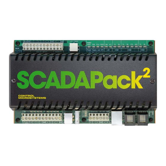
Page 8: Index Of Figures Figure 1: Scadapack 350 Controller
Figure 1: SCADAPack 350 Controller SCADAPack 350 Hardware Manual February 14, 2007... -
Page 9: Important Safety Information
WARNING ! USB PORTS MAY BE PERMANENTLY USED IN NON-HAZARDOUS APPLICATIONS. USB PORTS MAY BE USED FOR CORRECTIVE MAINT NANCE IN LOCATIONS CLASSIFIED AS HAZARDOUS BUT ARE KNOWN TO BE IN A NON-HAZARDOUS STATE. SCADAPack 350 Hardware Manual February 14, 2007... -
Page 10: Installation
I/O Bus cable routing and SCADAPack controller installation. 5606 Input/Output Module The SCADAPack 350 may include a optional 5606 lower IO module. The Model 5606 Input Output Module adds eight analog inputs, 32 digital inputs, and 16 relay digital outputs to the 5000 Series input/output system. -
Page 11: Figure 2: Scadapack 350 Layout
Figure 2: SCADAPack 350 Board Layout SCADAPack 350 Hardware Manual February 14, 2007... -
Page 12: Power Supply
Power Supply Overview and Power Requirements The SCADAPack 350 is powered from an 11V DC to 30V DC input power source. • Input power is applied to the positive (+) and negative (-) terminals on connector P3. Refer to section 16-Specifications of this manual for the minimum and maximum operating voltages and input power requirements. -
Page 13: System Grounding
I/O point terminals labeled GND are connected to chassis ground. Power Management Features The SCADAPack 350 provides a number of special features to reduce power consumption. Refer to Figure 3: Power Management for an overview of the power management features. These power management features are: •... -
Page 14: Com3 Serial Port Power Control
Lowering the CPU clock speed for reduced power mode. The SCADAPack 350 provides three internal digital outputs that can be operated by the user application to manage the power saving features. Internal digital outputs 8, 9 and 10 and the power management functions they control are described in the following sections. -
Page 15: Vloop Power Control
The 12V to 24V DC/DC converter is used to provide 24V DC for VLOOP power and for the 5305 Analog Output module. The converter should be turned on if the SCADAPack 350 is equipped with analog outputs for which 24V drive capability is required. Otherwise, the DC/DC converter can be turned off to conserve power. - Page 16 The 12V to 24V DC/DC converter is turned on when the LED power is enabled. This feature is provided for service and diagnostics. Refer to section 13.3-LED Power Control for further information on this feature. SCADAPack 350 Hardware Manual February 14, 2007...
-
Page 17: Analog Inputs
Analog Inputs The SCADAPack 350 provides eight analog input channels. This comprises of six single ended analog inputs available for external wiring and two internal for monitoring of onboard controller variables. The external inputs provide 15-bit resolution over the range of the input. Five external inputs can be configured for voltage or current mode. -
Page 18: Analog Input Wiring
5V. The first option is to use the SCADAPack 350 VLOOP Supply that steps up the input voltage to 24V. The stepped up voltage is available on the Analog Connector P10 and is labeled VLOOP. -
Page 19: Analog Input Mode Jumpers
Channels 0 through 4 can be user configured for either voltage or current operation, using jumper links. Refer to Figure 2: SCADAPack 350 Board Layout for the location of the analog input mode selection jumpers. A sample illustration of the analog input mode selection using jumpers J1-J5 is given in Figure 4: Analog Input Wiring. -
Page 20: Analog Outputs
Analog Outputs The SCADAPack 350 may include two analog output channels if this option was requested at time of purchase. Refer to the TelePACE or ISaGRAF software manuals for information on how to use the SCADAPack 350 Analog Outputs in application programs. Access to the analog output registers is achieved using a Register Assignment in TelePACE or I/O connection in ISaGRAF. - Page 21 Data Current 4.88µA 6552 16384 10mA 24576 15mA 32760 19.995mA SCADAPack 350 Hardware Manual February 14, 2007...
-
Page 22: Digital Outputs
(greater than 1H) are operated continuously at greater than 0.5Hz. The SCADAPack 350 also provides three internal digital outputs that can be controlled by the user application to manage power saving features unique to the SCADAPack 350. -
Page 23: Digital Inputs
Digital Inputs The SCADAPack 350 I/O Module provides eight universal digital inputs and outputs. The inputs are for use with dry contacts such as switches and relay contacts. The SCADAPack 350 provides the wetting current for the contacts. If LED power is enabled, the SCADAPack 350 continuously sources approximately 5mA wetting current into each dry contact input. - Page 24 0 = off 1 = on Internal COM3 (HMI) power. 0 = off 1 = on See section 4.4.1-COM3 Serial Port Power Control for details. SCADAPack 350 Hardware Manual February 14, 2007...
-
Page 25: Digital I/O Connection Examples
0 is shown connected to a 12V load that uses the same 12V power supply that powers the SCADAPack 350. Digital I/O point 4 is shown connected to a 24V load and external 24V-power supply. Digital I/O point 2 is shown monitoring a dry contact. Digital I/O point 5 is shown monitoring an open collector contact. -
Page 26: Counter Inputs
Counter Inputs The SCADAPack 350 has three counter inputs, identified as Counter 0, 1 and 2. Two of the counter inputs, Counter 1 and 2, are designed for millivolt level turbine meters. The third, Counter 0, is a high level digital input for use with open collector/drain output amplifiers. -
Page 27: Directly Connecting To Low Voltage Turbine Meters
4. Install jumper J10 on the ‘See J12’ position, as shown below. SCADAPack 350 See J12 Internal amplifier Counter 2 Int. Amplifier Figure 9: Setting Jumpers on Counter Input 2 for Low Voltage Turbine Meters SCADAPack 350 Hardware Manual February 14, 2007... -
Page 28: Connecting To Higher Voltage Turbine Meters
Your standalone amplifier may have a specific current requirement as specified by the manufacturer. As shown in the figure above, the SCADAPack 350 includes a 1000-ohm resistor from the counter input to the DC input power source, when the jumpers J11 and J12 are installed in the ‘Ext Amplifier’... -
Page 29: Connecting To Open Collector / Dry Contact Turbine Meters
Counter Inputs 1 and 2 can also used with conventional sources such as open collector transistors and contacts. In this scenario, the 1000 ohm pull-up resistors described above can be used if the SCADAPack 350 is powered from 12V. For Counter 1: 1. -
Page 30: Serial Communication
The following table shows the serial and protocol communication parameters supported by COM2. These parameters are set from TelePACE, ISaGRAF Workbench or from an application program running in the SCADAPack 350 controller. Default values are set when a Cold Boot or Service Boot is performed on the SCADAPack 350 controller. -
Page 31: Figure 9: Rj-45 Connector Pinout
Description This pin can be connected to the 5V power supply by (Output) installing a jumper at J14 on the SCADAPack 350. Warning: This 5V output is used to power Vision terminals and other Control Microsystems accessories. DO NOT apply 5V to this pin. - Page 32 This pin is set to a MARK just before and during transmission of data if half-duplex operation is selected. This pin is set to a SPACE when no data is being transmitted. The LED is ON for a MARK level. SCADAPack 350 Hardware Manual February 14, 2007...
-
Page 33: Com3 Rs-232 Serial Port
Connections to COM3 are made through a RJ-45 modular connector. COM3 supports six signals plus Ground and 5V power. The SCADAPack 350 COM3 is designed to be able to operate with the SCADAPack Vision operator interface and has several special features noted below. Two of the signals (DTR and DCD) are shared with the test signals used to detect the ON switch closure on the Vision interface, in a manner similar to the SCADAPack LP. -
Page 34: Figure 10: Rj-45 Connector Pinout
+5V is available on Pin 1 when turned on by the user under program control or, provided jumpers J15, J16 have their jumper links in the “Vision” position, when the SCADAPack 350 detects the contact closure of the ON switch of the SCADAPack Vision or the LEDs are turned on. - Page 35 This pin is set to a MARK just before and during transmission of data if half-duplex operation is selected. This pin is set to a SPACE when no data is being transmitted. The LED is ON for a MARK level. SCADAPack 350 Hardware Manual February 14, 2007...
-
Page 36: Rs-232 Wiring Examples
RS-232 COM port with a DTE device requiring handshaking lines. RS-232 COM port (DTE) 8 Pin connector + 5V See device specifications for pin numbers Figure 15: RS-232 DTE to RS-232 DTE with Handshaking SCADAPack 350 Hardware Manual February 14, 2007... -
Page 37: Rs-232 Cables
RJ-45 to DE-9S DTE This cable is used to connect from an RJ-45 based RS-232 port on the SCADAPack 350 controller to DE-9P connector on a DTE such as a PC. A 10 ft. long cable is available from Control Microsystems as part number 297217. -
Page 38: Rs-485 Serial Communication Ports
The following table shows the serial and protocol communication parameters supported by COM1. These parameters are set from TelePACE, ISaGRAF Workbench or from an application program running in the SCADAPack 350 controller. Default values are set when a Cold Boot or Service Boot is performed on the SCADAPack 350 controller. -
Page 39: Com2 Rs-485 Serial Port
The signal grounds of the RS-485 devices in the network are not connected together but instead are referenced to their respective incoming electrical grounds. The grounds of the RS-485 devices on the network must be within several volts of each other. The SCADAPack 350 ground is connected to the chassis. - Page 40 The signal grounds of the RS-485 devices in the network are not connected together but instead are referenced to their respective incoming electrical grounds. The grounds of the RS-485 devices on the network must be within several volts of each other. Controller ground is connected to the chassis. SCADAPack 350 Hardware Manual February 14, 2007...
-
Page 41: Rs-485 Bias Resistors
Description This pin can be connected to the 5V power supply by (Output) installing a jumper at J14 on the SCADAPack 350. Not used in RS-485 mode. Should be left open. Not used in RS-485 mode. Should be left open. -
Page 42: Rs-485 Wiring Examples
A typical RS-485 wiring example is shown below. COM1 is shown connected to a multivariable transmitter such as a Control Microsystems 4000 series MVT. The power for the transmitter can come from the SCADAPack 350 power input source or can be obtained from the 24V VLOOP output for possible power savings. -
Page 43: Ethernet Communication
Ethernet Communication The SCADAPack 350 controller has one 10/100Base-T Ethernet port. This is a single communications channel running at 10/100 Mb/s over unshielded, twisted - pair cabling, using differential signaling. It supports both half-duplex and full-duplex operation. The interface supports auto-negotiation for both the speed and half/ full-duplex mode selection. -
Page 44: Rj-45 Modular Connector For Ethernet
11.2 RJ-45 Modular Connector for Ethernet The SCADAPack 350 can be connected directly to a wall jack or hub using standard RJ-45 Category 5 patch cables. The following diagram shows the pin connections for the RJ-45 modular connector. SCADAPack 350 Hardware Manual... -
Page 45: Figure 16: Rj-45 Connector For Ethernet
This may limit the practical distance to less than 100m or 350 feet. The Ethernet cables should not be run in parallel with power or any cables that generate noise. SCADAPack 350 Hardware Manual February 14, 2007... -
Page 46: Usb Ports
12.1.2 Peripheral Port The peripheral port uses a USB series “B” receptacle. A SCADAPack 350 will not draw any significant power from the host over the USB peripheral port. The following diagram shows the connections of the peripheral USB port. -
Page 47: Operation
Operation 13.1 Operating Modes A SCADAPack 350 may start up in RUN, SERVICE, COLD BOOT, FACTORY BOOT, or REENTRY BOOT modes. • Start up in the RUN mode automatically executes Ladder Logic and C/C++ programs in the controller memory. •... -
Page 48: Cold Boot Mode
RUN mode. 13.1.3 Cold Boot Mode COLD BOOT mode is used after installing new controller firmware. When a SCADAPack 350 controller starts in COLD BOOT mode: • The default serial and Ethernet communication parameters are used (see section 10- Serial Communication and 11-Ethernet Communication for a description of the default parameters). -
Page 49: Boot Mode Effects
Flash File System reformatted C Applications started logic application started Communication settings on active interface retained Settings saved to non- volatile memory ladder logic in flash is erased All protocols are set to defaults SCADAPack 350 Hardware Manual February 14, 2007... -
Page 50: Sleep Mode
13.1.6 Sleep Mode A SCADAPack 350 Controller is capable of extremely low power operation when in sleep mode. The controller enters the sleep mode under control of the application program. During sleep mode the following happen: • All programs stop executing. -
Page 51: Power Consumption
Reduced Disabled Disabled Sleep 13.2 LED Indicators There are 25 LEDs on SCADAPack 350. All LEDs can be disabled to conserve power. The table below describes the LEDs. Function Power On when operating and the LEDs are enabled. Mode Off when the LEDs are disabled. -
Page 52: Jumpers
Most headers on the SCADAPack 350 are user configurable and are described in the appropriate sections of this manual. Some headers and jumpers on the controller are reserved for manufacturing and test functions. Refer to Figure 2: SCADAPack 350 Board Layout for the location of all jumpers. -
Page 53: I/O Module Error Indication
1 second of delay), this indicates the register assignment is not valid. To correct this problem, initialize the register assignment from the TelePACE software, or alternatively, perform a COLD BOOT as described in section 13.1.3-Cold Boot Mode section of this manual. The status LED should stop flashing. SCADAPack 350 Hardware Manual February 14, 2007... -
Page 54: Maintenance
Maintenance The SCADAPack 350, as with all other SCADAPack controllers, requires little maintenance. The Power Mode LED indicates the status of the 5V supply. If the LED is off, the on board fuse F1 may require replacing. If the program is lost during power outages, the lithium battery may require replacement. - Page 55 7. Cold boot the controller. (Refer to section 13.1.3- Cold Boot Mode in of this manual for the Cold Boot procedure.) WARNING: If a cold boot is not done the behavior of the controller is unpredictable. 8. The controller may now be programmed. SCADAPack 350 Hardware Manual February 14, 2007...
-
Page 56: Troubleshooting
The LED is dim. This is normal operation when the controller is in low power mode or sleep mode, or when the LEDs are turned off. Check the controller digital I/Os are in the register assignment. SCADAPack 350 Hardware Manual February 14, 2007... -
Page 57: Digital Outputs
Input LED does not come Check the input signal at the termination block. It on when input signal is should be at least 50% of the counter input range. applied. Check the LEDs are turned on. SCADAPack 350 Hardware Manual February 14, 2007... -
Page 58: Specifications
Specifications Disclaimer: Control Microsystems reserves the right to change product specifications without notice. For more information visit www.controlmicrosystems.com 16.1 General 6 and 12 pole, removable terminal blocks. I/O Terminations 12 to 22 AWG 15A contacts 8.40 inch (213mm) wide Dimensions 5.00 inch (127 mm) high... -
Page 59: Usb
COM1 transmitted data (TX) LED received data (RX) LED COM2 transmitted data (TX) LED clear to send (CTS) LED data carrier detect (DCD) LED received data (RX) LED COM3 transmitted data (TX) LED SCADAPack 350 Hardware Manual February 14, 2007... -
Page 60: Power Supply
Vloop: 24V at 0.14A available for the 5 analog inputs and 2 optional analog outputs 85%, 12Vdc input, full load Efficiency 16.7 I/O Capacity Maximum 40 I/O modules. 5000 Series I/O Refer to the System Configuration Guide for further details. Expansion Capacity SCADAPack 350 Hardware Manual February 14, 2007... -
Page 61: Analog Inputs
ANSI/IEEE C37.90.1-1989 Protection 0.5ms to 2ms for 10% to 90% signal change Response Time 24V boost power supply off: Vin X output current. Power 24V boost power supply on: 27 X output current. Requirements SCADAPack 350 Hardware Manual February 14, 2007... -
Page 62: Counter Inputs
ON input requires less than 100Ω contact resistance. Contact OFF input requires greater than 50kΩ contact resistance. Resistance Cable contact capacitance not to exceed 0.033uF, typically 1600ft (500m). 2.5kV surge withstand capability as per ANSI/IEEE Transient SCADAPack 350 Hardware Manual February 14, 2007... - Page 63 C37.90.1-1989 Protection Common ground return connected to Chassis Ground. Isolation SCADAPack 350 Hardware Manual February 14, 2007...
-
Page 64: Approvals And Certifications
Standards and therefore conforms with the requirements of Council Directive 89/336/EEC (as amended) relating to electromagnetic compatibility and is eligible to bear the CE mark. The Low Voltage Directive is not applicable to this product. SCADAPack 350 Hardware Manual February 14, 2007...
Need help?
Do you have a question about the SCADAPack 350 and is the answer not in the manual?
Questions and answers