
Related Manuals for Control Microsystems SCADAPack LP


Summary of Contents for Control Microsystems SCADAPack LP
- Page 1 SCADAPack LP Hardware Manual CONTROL MICROSYSTEMS SCADA products... for the distance 48 Steacie Drive Telephone: 613-591-1943 Kanata, Ontario Facsimile: 613-591-1022 K2K 2A9 Technical Support: 888-226-6876 Canada 888-2CONTROL...
- Page 2 Printed in Canada. Trademarks TeleSAFE, TelePACE, SmartWIRE, SCADAPack, TeleSAFE Micro16 and TeleBUS are registered trademarks of Control Microsystems Inc. All other product names are copyright and registered trademarks or trade names of their respective owners. Material used in the User and Reference manual section titled SCADAServer OLE Automation Reference is distributed under license from the OPC Foundation.
-
Page 3: Table Of Contents
Analog Inputs Data Format ................15 ANALOG OUTPUTS ................... 17 Current Outputs.................... 17 Voltage Outputs ................... 17 Analog Outputs Data Format ............... 17 DIGITAL OUTPUTS..................19 DIGITAL INPUTS..................20 Digital I/O Connection Examples..............21 SCADAPack LP Hardware Manual May 26, 2006... - Page 4 LED Power Control ..................35 11.4 Jumpers ....................... 35 11.5 Status LED ....................36 11.5.1 I/O Module Error Indication ..............36 11.5.2 Register Assignment Checksum Error............ 36 MAINTENANCE................... 37 12.1 Fuses ......................37 SCADAPack LP Hardware Manual May 26, 2006...
- Page 5 Counter Inputs....................44 14.10 Digital Inputs/Outputs................... 45 APPROVALS AND CERTIFICATIONS ............46 Index of Figures Figure 1: SCADAPack LP Controller ................... 7 Figure 2: SCADAPack LP Board Layout................9 Figure 3: Power Management................... 11 Figure 4: Analog Input Wiring ................... 15 Figure 5: Analog Output Wiring..................
-
Page 6: Overview
The I/O capacity of the SCADAPack LP can be expanded using 5000 Series I/O modules. A maximum of forty 5000 Series I/O modules may be used for a total expansion capacity of 512 digital inputs, 512 digital outputs, 128 analog inputs, 64 analog outputs and 64 counter inputs. -
Page 7: Important Safety Information
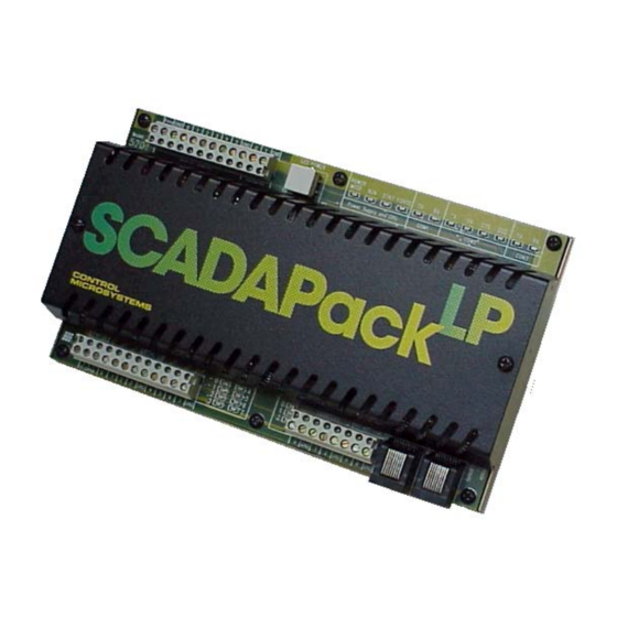
EXPLOSION HAZARD – WHEN IN HAZARDOUS LOCATIONS, TURN OFF POWER BEFORE REPLACING OR WIRING MODULES. WARNING ! EXPLOSION HAZARD - DO NOT DISCONNECT EQUIPMENT UNLESS POWER HAS BEEN SWITCHED OFF OR THE AREA IS KNOWN TO BE NONHAZARDOUS. SCADAPack LP Hardware Manual May 26, 2006... - Page 8 Figure 1: SCADAPack LP Controller SCADAPack LP Hardware Manual May 26, 2006...
-
Page 9: Installation
• Push the connector onto the pins. Apply even pressure to both ends on the connector. There are six connectors for field wiring. Refer to Figure 2: SCADAPack LP Board Layout for connector locations. • The two RS-232 communication ports, COM 2 and COM 3, connect to 8 pin modular jacks. -
Page 10: Figure 2: Scadapack Lp Board Layout
Figure 2: SCADAPack LP Board Layout SCADAPack LP Hardware Manual May 26, 2006... -
Page 11: Power Supply
SCADAPack LP. The DC power-input voltage is used to generate 5V for the SCADAPack LP circuitry. The output capacity of the 5V supply is sufficient to power the SCADAPack LP and a SCADAPack Vision operator interface with 100mA remaining capacity for a limited number of 5000 Series I/O modules. -
Page 12: Com3 Serial Port Power Control
The DC/DC converter output can be used to power analog input current loops or other instrumentation. This output, VLOOP, is controlled for intermittent or continuous operation. Turning the VLOOP output off when it is not required can save considerable electrical power. SCADAPack LP Hardware Manual May 26, 2006... -
Page 13: To 24V Dc/Dc Converter Control
The 12V to 24V DC/DC converter is used to provide 24 Vdc for VLOOP power and for the 5305 Analog Output module. The converter should be turned on if the SCADAPack LP is equipped with analog outputs for which 24V drive capability is required. Otherwise, the DC/DC converter can be turned off to conserve power. -
Page 14: Analog Inputs
There are six single ended analog inputs available to the user. These analog inputs provide 15-bit resolution over the entire range of the input. The analog inputs are transient protected and share a common return (GND) that is connected to the chassis. Refer to Figure 2: SCADAPack LP Board Layout for the location of P9. -
Page 15: Analog Input Connections
5V. The first option is to use the SCADAPack LP VLOOP Supply that steps up the input voltage to 24V. The stepped up voltage is available on the Analog Connector P10 and is labeled VLOOP. There is sufficient power available here for the five analog inputs and two analog outputs all operating at 20mA. -
Page 16: Analog Input Range Jumpers
When an analog input is configured for current, 20mA input is represented with 14 bits of data. There is 100% over range. The input resolution is 1.22µA/count. The channel 5 analog input is configured for voltage. 32.768V is represented with 15 bits of data. The input resolution is 0.001V/count. SCADAPack LP Hardware Manual May 26, 2006... - Page 17 The following table shows the A/D output value for several input signals. Current Voltage Voltage A/D Output Channel 0-4 Channel 0-4 Channel 5 1.22µA 0.305mV 0.001V 1.0V 3.277V 3277 10mA 2.5V 8.192V 8192 20mA 5.0V 16.384V 16384 39.999mA 9.9997V 32.767V 32767 SCADAPack LP Hardware Manual May 26, 2006...
-
Page 18: Analog Outputs
6 Analog Outputs The SCADAPack LP may include two channels of analog output if this option was requested at time of purchase. Refer to the appropriate software manual for information on using the SCADAPack LP Analog Outputs in application programs. For TelePACE applications refer to the Register Assignment for SCADAPack LP I/O module and for ISaGRAF applications refer to the I/O Complex Equipment for SCADAPack LP I/O. - Page 19 D/A Value Current 4.88µA 6552 16384 10mA 24576 15mA 32760 19.995mA SCADAPack LP Hardware Manual May 26, 2006...
-
Page 20: Digital Outputs
(greater than 1H) are operated continuously at greater than 0.5Hz. The SCADAPack LP also provides three internal digital outputs that can be controlled by the user application to manage power saving features unique to the SCADAPack LP. -
Page 21: Digital Inputs
8 Digital Inputs The SCADAPack LP I/O Module provides eight universal digital inputs and outputs. The inputs are for use with dry contacts such as switches and relay contacts. The SCADAPack LP provides the wetting current for the contacts. If LED power is enabled, the SCADAPack LP continuously sources approximately 5mA wetting current into each dry contact input. -
Page 22: Digital I/O Connection Examples
0 is shown connected to a 12V load that uses the same 12V power supply that powers the SCADAPack LP. Digital I/O point 4 is shown connected to a 24V load and external 24V-power supply. Digital I/O point 2 is shown monitoring a dry contact. Digital I/O point 5 is shown monitoring an open collector contact. -
Page 23: Counter Inputs
9 Counter Inputs The SCADAPack LP has three counter inputs, identified as Counter 0, 1 and 2. Two of the counter inputs, Counter 1 and 2, are designed for millivolt level turbine meters. The third, Counter 0, is a high level digital input for use with open collector/drain output amplifiers. -
Page 24: Figure 8: Counter Jumpers
DC input power source. This is the recommended wiring for a Halliburton Low Power Pre-Amp when the SCADAPack LP is powered from 12V. If this resistor is not suitable for your external amplifier then do not connect the jumper in either position. On Counter 1, the J11 jumper would be removed. -
Page 25: Serial Communication
The following table shows the serial and protocol communication parameters supported by COM2. These parameters are set from TelePACE, ISaGRAF Workbench or from an application program running in the SCADAPack LP controller. Default values are set when a Cold Boot or Service Boot is performed on the SCADAPack LP controller. - Page 26 • +5V is only available on Pin 1 when a jumper is installed on J13. Refer to the Figure 2: SCADAPack LP Board Layout for the location of J13. • The low power transmitters used in COM2 generate 0 to 5V levels. This is less than the RS-232 specification but still compatible with all RS-232 receivers.
-
Page 27: Com3 Rs-232 Serial Port
The following table shows the serial and protocol communication parameters supported by COM3. These parameters are set from TelePACE, ISaGRAF Workbench or from an application program running in the SCADAPack LP controller. Default values are set when a Cold Boot or Service Boot is performed on the SCADAPack LP controller. -
Page 28: Rs-232 Wiring Examples
• +5V is available on Pin 1 when turned on by the user under program control, when the SCADAPack LP detects the contact closure of the ON switch of the SCADAPack Vision or when the LED Power is ON. •... -
Page 29: Dte To Dte With Handshaking
DCE devices require different wiring. The handshaking lines must be connected in most cases. Note that many DCE devices are half-duplex. Select half-duplex operation with these devices. The diagram below shows common connection of a SCADAPack with a DCE device requiring handshaking lines. SCADAPack LP Hardware Manual May 26, 2006... -
Page 30: Rs-232 Cables
This cable is used to connect from an RJ-45 based RS-232 port on the SCADAPack controller to DE-9P connector on a DTE such as a PC. A 10 ft. long cable is available from Control Microsystems as part number 297217. -
Page 31: To De-9P Dce
The following table shows the serial and protocol communication parameters supported by COM1. These parameters are set from TelePACE, ISaGRAF Workbench or from an application program running in the SCADAPack LP controller. Default values are set when a Cold Boot or Service Boot is performed on the SCADAPack LP controller. -
Page 32: Rs-485 Bias Resistors
The signal grounds of the RS-485 devices in the network are not connected together but instead are referenced to their respective incoming electrical grounds. The grounds of the RS-485 devices on the network must be within several volts of each other. The SCADAPack LP ground is connected to the chassis. -
Page 33: Figure 9: Rs-485 Wiring
SCADAPack LP P3 – DC Power In P6 – RS-485 – + PWR 12Vdc Power Supply – PWR Rosemount 3095 MVT Figure 9: RS-485 Wiring SCADAPack LP Hardware Manual May 26, 2006... -
Page 34: Operation
11.1 Operating Modes SCADAPack LP Controllers may start up in RUN, SERVICE or COLD BOOT mode. Start up in the RUN mode automatically executes TelePACE Ladder Logic and TelePACE C programs in the controller memory. Start up in the SERVICE mode stops the programs to allow reprogramming and controller initialization. -
Page 35: Sleep Mode
6. The COM3 Test1 to Test2 pins are connected together indicating the SCADAPack Vision is to be turned on. 11.2 LED Indicators There are 23 LEDs on SCADAPack LP. All LEDs can be disabled to conserve power. The table below describes the LEDs. SCADAPack LP Hardware Manual May 26, 2006... -
Page 36: Led Power Control
11.3 LED Power Control The SCADAPack LP controller board can disable the LEDs on the controller board and the 5000 Series I/O modules to conserve power. This is particularly useful in solar powered or unattended installations. -
Page 37: Status Led
1 second of delay), this indicates the register assignment is not valid. To correct this problem, initialize the register assignment from the TelePACE software, or alternatively, perform a COLD BOOT as described in section 11.1.3-Cold Boot Mode of this manual. The status LED should stop flashing. SCADAPack LP Hardware Manual May 26, 2006... -
Page 38: Maintenance
12 Maintenance The SCADAPack LP controller requires little maintenance. The Power Mode LED indicates the status of the 5V supply. If the LED is off, the on board fuse F1 may require replacing. If the program is lost during power outages, the lithium battery may require replacement. - Page 39 7. Cold boot the controller. (Refer to section 11.1.3-Cold Boot Mode in of this manual for the Cold Boot procedure.) Warning: If a cold boot is not done the behavior of the controller is unpredictable. 8. The controller may now be programmed. SCADAPack LP Hardware Manual May 26, 2006...
-
Page 40: Troubleshooting
Check the external device. device is not activated. Output LED and output are Check that the output is not forced on. on when they should be off. SCADAPack LP Hardware Manual May 26, 2006... -
Page 41: Counter Inputs
50% of the counter input range. applied. The LED is dim. This normal operation when the controller is in low power mode or sleep mode. SCADAPack LP Hardware Manual May 26, 2006... -
Page 42: Specifications
14 Specifications Disclaimer: Control Microsystems reserves the right to change product specifications without notice. For more information visit www.controlmicrosystems.com 14.1 General 8 and 10 pole, removable terminal blocks. I/O Terminations 12 to 22 AWG 15A contacts 8.40 inch (213mm) wide Dimensions 5.00 inch (127 mm) high... -
Page 43: Visual Indicators
Forced I/O LED 8 LEDs Digital Inputs / Outputs 3 LEDs Counters LED power toggle Push-button 14.5 Power Supply 30V maximum DC power Input 10.0 to 11.5V turn on 9.5V typical turn off SCADAPack LP Hardware Manual May 26, 2006... -
Page 44: I/O Capacity
Calibration constants stored in on board Calibration microcontroller EEPROM. 27 dB at 60 Hz. Normal mode rejection 10V/20mA inputs clamped at 12V. Over-scale Input Capacity (without damage) Transient: 2.5kV surge withstand capability as per ANSI/IEEE C37.90.1-1989 SCADAPack LP Hardware Manual May 26, 2006... -
Page 45: Analog Outputs
Minimum input 150mVp-p at 150Hz. Sensitivity Minimum input 650mVp-p at 5kHz. Minimum input 750mVp-p at 10kHz. Maximum input 4Vp-p using internal amplifier. Maximum input 10Vp-p without internal amplifier. Counter 1 and 2 Maximum frequency 10KHz. Dry Contact SCADAPack LP Hardware Manual May 26, 2006... -
Page 46: Digital Inputs/Outputs
OFF input requires greater than 50kΩ contact resistance. Cable contact capacitance not to exceed 0.033uF, typically 1600ft (500m). 2.5kV surge withstand capability as per ANSI/IEEE Transient C37.90.1-1989 Protection Common ground return connected to Chassis Ground. Isolation SCADAPack LP Hardware Manual May 26, 2006... -
Page 47: Approvals And Certifications
Standards and therefore conforms with the requirements of Council Directive 89/336/EEC (as amended) relating to electromagnetic compatibility and is eligible to bear the CE mark. The Low Voltage Directive is not applicable to this product. SCADAPack LP Hardware Manual May 26, 2006...
Need help?
Do you have a question about the SCADAPack LP and is the answer not in the manual?
Questions and answers