Table of Contents

Related Manuals for Control Microsystems SCADAPack 32P


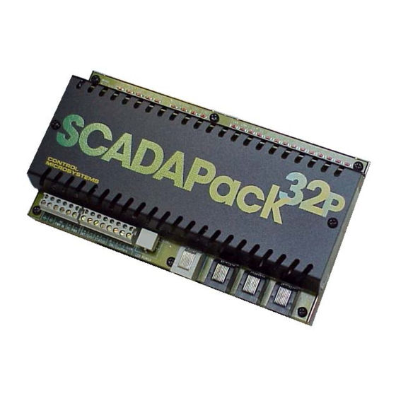
Summary of Contents for Control Microsystems SCADAPack 32P
- Page 1 SCADAPack 32P Controller Hardware Manual CONTROL MICROSYSTEMS SCADA products... for the distance 48 Steacie Drive Telephone: 613-591-1943 Kanata, Ontario Facsimile: 613-591-1022 K2K 2A9 Technical Support: 888-226-6876 Canada 888-2CONTROL...
- Page 2 Printed in Canada. Trademarks TeleSAFE, TelePACE, SmartWIRE, SCADAPack, TeleSAFE Micro16 and TeleBUS are registered trademarks of Control Microsystems Inc. All other product names are copyright and registered trademarks or trade names of their respective owners. Material used in the User and Reference manual section titled SCADAServer OLE Automation Reference is distributed under license from the OPC Foundation.
-
Page 3: Table Of Contents
DTE to DTE with Handshaking ............... 19 4.2.3 DTE to DCE with Handshaking............... 19 RS-232 Cables..................... 20 4.3.1 RJ-45 to DE-9S DTE ................20 4.3.2 RJ-45 to DE-9P DCE ................20 RS-485 Serial Communication Port ............. 20 SCADAPack 32P Controller Hardware Manual May 26, 2006... - Page 4 RJ-45 Modular Connector for Ethernet ........... 27 OPERATION....................29 Run Mode ....................29 Service Mode ....................29 Cold Boot Mode ................... 30 SCADAPack 32P LED Indicators ..............30 LED Power Control ..................31 Status LED and Output ................31 6.6.1 I/O Module Error Indication ..............32 6.6.2...
- Page 5 Power Supply ....................38 I/O Capacity ....................39 Digital Inputs ....................39 Digital Outputs....................39 Approvals and Certifications................. 39 Index of Figures Figure 1: SCADAPack 32P ....................5 Figure 2: 5232 Controller Module ..................8 SCADAPack 32P Controller Hardware Manual May 26, 2006...
-
Page 6: Overview
The RS-232 and RS-485 ports operate at baud rates from 300 baud to 38400 baud. Using 5000 Series I/O modules can expand the I/O capacity of SCADAPack 32P Controllers. A maximum of forty 5000 Series I/O modules may be connected for an expansion of up to 512 digital outputs, 512 digital inputs, 128 analog inputs, 32 counters and 32 analog outputs. -
Page 7: Important Safety Information
EXPLOSION HAZARD – WHEN IN HAZARDOUS LOCATIONS, TURN OFF POWER BEFORE REPLACING OR WIRING MODULES. WARNING ! EXPLOSION HAZARD - DO NOT DISCONNECT EQUIPMENT UNLESS POWER HAS BEEN SWITCHED OFF OR THE AREA IS KNOWN TO BE NONHAZARDOUS. SCADAPack 32P Controller Hardware Manual May 26, 2006... -
Page 8: Installation
SCADAPack 32P controller installation. Field Wiring Connections SCADAPack 32P controllers use screw termination style connectors for termination of field wiring. These connectors can accommodate solid or stranded wires from 22 to 12 AWG. The termination connectors fit over pins on the 5232 controller board. The connectors are removable allowing replacement of the SCADAPack 32P Controller without disturbing the field wiring. -
Page 9: Power Supply
Figure 2: 5232 Controller Module Power Supply The SCADAPack 32P controller is primarily a DC input powered device but can be powered with 16Vac under some conditions. The power supply requirements for the 5232 Controller board are each explained in the following sections. -
Page 10: Recommended Ac Power Supply Configuration
3.2.3 Recommended AC Power Supply Configuration This configuration uses a single Class 2 transformer to power the SCADAPack 32P. 24V are available on the controller module connector P3. They are used to power the analog circuitry for the analog input circuits on additional 5000 Series Analog I/O modules. -
Page 11: Recommended 24Vdc Battery Supply Configuration
Recommended 24VDC Battery Supply Configuration This configuration uses a high capacity source, such as a battery, to power the SCADAPack 32P. An 11 – 24VDC battery source is applied with the positive to the AC PWR IN terminal 3 and the negative to DC PWR (-). -
Page 12: System Grounding
In most applications, it is desirable to ground the system by connecting the system power supply common, to the chassis or panel ground. On the SCADAPack 32P, the – side of both the 5V and the 24V supplies are connected to the enclosure. Pins 1 and 2 on P3 are connected internally to the enclosure. -
Page 13: Digital /Counter Inputs
For ISaGRAF applications use the ainbatt I/O connection to read the lithium battery voltage. Digital /Counter Inputs The SCADAPack 32P has three Digital / Counter inputs. These inputs are labeled DIN\Counter 0, 1 and 2 on the P4 terminal connector. These inputs operate as AC or DC digital inputs or as counter inputs. -
Page 14: Interrupt Input
Interrupt Input The SCADAPack 32P has one Interrupt digital input. This input is labeled DINT on the P4 terminal connector. This input operates as a DC digital input or as a counter input. • For DC input the maximum input voltage is 28V and the minimum voltage to turn the input ON is 2.5V. - Page 15 24V coil with greater than 400Ω resistance. STATUS – Relay Coil Specifications: • 24 V • > 400 ohms – • < 60mA NO COM NC ALARM CONTACTS: closed during power failures and fault conditions. SCADAPack 32P Controller Hardware Manual May 26, 2006...
-
Page 16: Serial Communication
The following table shows the serial and protocol communication parameters supported by COM1. These parameters are set from TelePACE, ISaGRAF Workbench or from an application program running in the SCADAPack 32P controller. Default values are set when a Cold Boot or Service Boot is performed on the SCADAPack 32P controller. -
Page 17: Com2 Rs-232 Serial Port
The following table shows the serial and protocol communication parameters supported by COM2. These parameters are set from TelePACE, ISaGRAF Workbench or from an application program running in the SCADAPack 32P controller. Default values are set when a Cold Boot or Service Boot is performed on the SCADAPack 32P controller. -
Page 18: Modular Connector For Rs-232
Serial communication ports COM1, COM2 and COM4 are located on the SCADAPack 32P SCADAPack 32P. These are RS-232 serial ports using a 8-pin female RJ-45 connectors configured as Data Terminal Equipment (DTE). The recommended specification for RS-232 cable length is a maximum of 50 feet or 15.2 meters. -
Page 19: Rs-232 Wiring Examples
DCE (Data Communications Equipment) devices. The simplest connection requires only 3 wires: RxD, TxD and signal ground. The following diagram shows a common RS-232 COM port to DTE device. RS-232 COM port (DTE) + 5V See device specifications for pin numbers SCADAPack 32P Controller Hardware Manual May 26, 2006... -
Page 20: Dte To Dte With Handshaking
DCE devices are half duplex. Select half-duplex operation with these devices. The diagram below shows common connection of a SCADAPack with a DCE device requiring handshaking lines. RS-232 COM port (DTE) + 5V See device specifications for pin numbers SCADAPack 32P Controller Hardware Manual May 26, 2006... -
Page 21: Rs-232 Cables
RJ-45 to DE-9S DTE This cable is used to connect from an RJ-45 based RS-232 port on the SCADAPack 32P controller to DE-9P connector on a DTE such as a PC. A 10 ft. long cable is available from Control Microsystems as part number 297217. -
Page 22: Modular Connector For Rs-485
4.4.2 RS-485 Bias Resistors The RS-485 receiver inputs on the SCADAPack 32P controller are biased to ensure that that received data is driven to a valid state (space) when there are no active drivers on the network. The value of these bias resistors is 4700 ohms from Ground to the –Rx input and 4700 ohms from +5V to the +Rx... -
Page 23: Rs-485 Termination Resistors
RS-485 networks are generally terminated with 120 ohm resistors on each end. The required 120 ohm resistor is built into the SCADAPack 32P controller. When these termination resistors are used, the biasing generally has to be increased in order to generate at least 0.2V across the +/–Rx input. -
Page 24: Two Wire Mode
+Rx and –Tx must be connected to the –Rx. This pair of wires becomes the transmitting and receiving pair. The following diagram shows the wiring details for a two wire connection. SCADAPack 32P Controller Hardware Manual May 26, 2006... -
Page 25: Rs-485 Cable
+ TX RS-485 Cable This cable is used to connect from an RJ-45 based RS-485 port on the SCADAPack 32P controller to other RS-485 devices. The cable has a RJ-45 connector on one end and stripped wires at the other end. - Page 26 RJ45 Function Wire color Do not connect. Green SCADAPack 32P Controller Hardware Manual May 26, 2006...
-
Page 27: Ethernet Communication
The following table shows the TCP/IP parameters supported by the LAN port. These parameters are set from the ISaGRAF Workbench or from an application program running in the SCADAPack 32P controller. Default values are set when a Cold Boot is performed on the SCADAPack 32P controller. Parameter Supported Values In the format 255.255.255.255... -
Page 28: Modular Connector For Ethernet
5.1.3 RJ-45 Modular Connector for Ethernet The SCADAPack 32P can be connected directly to a wall jack or hub using standard RJ-45 Category 5 patch cables. The following diagram shows the pin connections for the RJ-45 modular connector. SCADAPack 32P Controller Hardware Manual... - Page 29 This may limit the practical distance to less than 100m or 350 feet. The Ethernet cables should not be run in parallel with power or any cables that generate noise. SCADAPack 32P Controller Hardware Manual May 26, 2006...
-
Page 30: Operation
Continue holding the LED POWER button until the STAT LED turns on. • Release the LED POWER button. Note: If the LED POWER button is released before the STAT LED turns on, the SCADAPack 32P controller will start in RUN mode. SCADAPack 32P Controller Hardware Manual... -
Page 31: Cold Boot Mode
SCADAPack 32P controller will start in SERVICE mode. SCADAPack 32P LED Indicators There are twenty-three LEDs on the SCADAPack 32P SCADAPack 32P. These LEDs are used to indicate the operational status of the controller. All LEDs except the 5V LED can be disabled to conserve power. -
Page 32: Led Power Control
SCADAPack 32P is used in solar powered or unattended installations. The LEDS LED on the SCADAPack 32P indicates the LED power state. This LED is on when power to the LEDs is enabled and off when power to the LEDs is disabled. See section 3.1.1- 5232 Controller Board Field Wiring Connectors for the location of the LEDS LED. -
Page 33: I/O Module Error Indication
It indicates the custom application is requesting I/O operations faster than the system can process them and that the queue of pending operations is full. The custom application should reduce the rate at which it makes requests. SCADAPack 32P Controller Hardware Manual May 26, 2006... -
Page 34: Configuration Switches
• Do not use filtering for high speed counting applications. SCADAPack 32P SCADAPack 32P SW1, switches Filter 0, Filter 1 and Filter 2 switches control the input filter functions. • Filter 0 for DIN/Counters input 0. -
Page 35: Line Frequency Selection
6.7.2 Line Frequency Selection The SCADAPack 32P Option Switch 3 selects the line frequency option. The diagram below shows the switch settings for selecting the line frequency. 60 Hz Operation 50 Hz Operation How to Set the Frequency Switch: •... -
Page 36: Maintenance
The SCADAPack 32P controllers require little maintenance. The 5V power LED indicates the status of the 5V supply. If the LED is off, and the SCADAPack 32P controller is powered using the integrated power supply, on board fuse F1 or F2 may require replacing. If the LED is off, and the SCADAPack 32P controller is powered using a 5103 power supply fuse F1 (5V) or F2 (24V) on the 5103 may require replacing. - Page 37 Cold boot the controller. (Refer to section 6.3-Cold Boot Mode section in of this manual for the Cold Boot procedure.) Warning: If a cold boot is not done the behavior of the controller is unpredictable. • The controller may now be programmed. SCADAPack 32P Controller Hardware Manual May 26, 2006...
-
Page 38: Specifications
Specifications Disclaimer: Control Microsystems reserves the right to change product specifications without notice. For more information visit www.controlmicrosystems.com General I/O Terminations 6,8,9 and 10 pole, removable terminal blocks. 12 to 22 AWG 15A contacts Dimensions 8.40 inch (213mm) wide 6.13 inch (155mm) high 1.75 inch (44mm) deep... -
Page 39: Visual Indicators
10.7V typical turn on 9V typical turn off 5 Volt Power 5V at 1.3A capacity Output 5V at 500 mA required by SCADAPack 32P DC power 20-24V with 1.0Vp-p maximum ripple. Output 300mA available at 5V/0.5A, de-rate linearly to 100mA available at 5V/1.3A... -
Page 40: I/O Capacity
EN61000-6-2: 1999 Electromagnetic Compatibility Generic Immunity Standards Immunity for Industrial Environments Declaration This product conforms to the above Emissions and Immunity Standards and therefore conforms with the requirements of Council Directive 89/336/EEC (as amended) relating to SCADAPack 32P Controller Hardware Manual May 26, 2006... - Page 41 The Low Voltage Directive is not applicable to this product. SCADAPack 32P Controller Hardware Manual May 26, 2006...
Need help?
Do you have a question about the SCADAPack 32P and is the answer not in the manual?
Questions and answers