
Related Manuals for Moxa Technologies AIG-500 Series


Summary of Contents for Moxa Technologies AIG-500 Series
- Page 1 AIG-500 Series Hardware User’s Manual Version 1.0, September 2021 www.moxa.com/product © 2021 Moxa Inc. All rights reserved.
- Page 2 AIG-500 Series Hardware User’s Manual The software described in this manual is furnished under a license agreement and may be used only in accordance with the terms of that agreement. Copyright Notice © 2021 Moxa Inc. All rights reserved. Trademarks The MOXA logo is a registered trademark of Moxa Inc.
-
Page 3: Table Of Contents
Table of Contents Introduction ............................1-1 Model Descriptions ..........................1-2 Package Checklist ..........................1-2 Product Features ..........................1-2 Product Specifications ......................... 1-2 Hardware Introduction........................2-1 Appearance ............................2-2 Dimensions ............................2-3 LED Indicators ............................ 2-3 Reboot .............................. 2-3 Reset to Default ..........................2-4 Real-time Clock .......................... -
Page 4: Introduction
With the use of the ThingsPro Proxy utility, the device provisioning process is easier than ever. Thanks to the robust OTA function, you never have to worry about system failure during software upgrades. With the secure boot function enabled, you can enable the booting process of AIG-500 Series to prevent malicious software injection. -
Page 5: Model Descriptions
AIG-500 Series HW UM Introduction Model Descriptions The AIG-500 Series includes the following models: • AIG-501-T-AZU-LX: Advanced IIoT gateway with Intel Atom® quad-core 1.91 GHz processor, 1 VGA port, 4 DIs, 4 DOs, ThingsPro Edge and Azure IoT Edge software, -40 to 70°C operating temperature AIG-501-T-US-AZU-LX: Advanced IIoT gateway with Intel Atom®... -
Page 6: Hardware Introduction
LED indicators allow you to monitor device performance and quickly identify issues, and the multiple ports can be used to connect a variety of devices. The AIG-500 Series comes with a reliable and stable hardware platform that lets you devote the bulk of your time to application development. In this chapter, we provide basic information about the device’s hardware and its various components. -
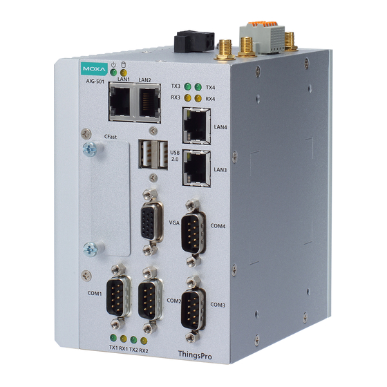
Page 7: Appearance
AIG-500 Series HW UM Hardware Introduction Appearance Top Panel View Front Panel View Bottom Panel View... -
Page 8: Dimensions
AIG-500 Series HW UM Hardware Introduction Dimensions LED Indicators The function of each LED is described in the table below: LED Name Status Function Power Green Power is ON No power Storage (CFast) Yellow Blinking Data is being written to or read from the storage... -
Page 9: Reset To Default
AIG-500 Series HW UM Hardware Introduction Reset to Default Refer to ThingsPro Edge user manual to execute Reset to Default function. No hardware button is available for resetting the device to factory default. Real-time Clock The real-time clock is powered by a non-chargeable battery. We strongly recommend that you do not replace the lithium battery without help from a qualified Moxa support engineer. -
Page 10: Wall Mounting (Optional)
AIG-500 Series HW UM Hardware Introduction Removal STEP 1: To unmount the AIG-500, pull down the latch provided at the base of the mounting kit with a screwdriver. STEPS 2 & 3: Slightly pull the AIG-500 forward and lift it up to detach it from the DIN rail. -
Page 11: Hardware Connection Description
Hardware Connection Description In this chapter, we describe how to connect the AIG-500 to a network and other devices. The following topics are covered in this chapter: Wiring Requirements Connecting the Power Grounding the Unit Connecting to the Network ... -
Page 12: Wiring Requirements
AIG-500 Series HW UM Hardware Connection Description Wiring Requirements In this section, we describe how to connect various devices to the AIG-500. Be sure to read and follow these common safety precautions before proceeding with the installation of any electronic device: •... -
Page 13: Grounding The Unit
AIG-500 Series HW UM Hardware Connection Description Grounding the Unit There is a grounding connector on the top panel of the device. Use this connector to connect a well- grounded mounting surface, such as a metal panel. Grounding and wire routing help limit the effects of noise due to electromagnetic interference (EMI). -
Page 14: Connecting The Digital Inputs And Digital Outputs
AIG-500 Series HW UM Hardware Connection Description Connecting the Digital Inputs and Digital Outputs There are four digital inputs and four digital outputs on the top panel. Refer to the figure on the left for detailed pin definitions. NOTE Do not use the Source port for safety reasons. -
Page 15: Installing The Wi-Fi Module (Aig-501-T-Azu-Lx Only)
AIG-500 Series HW UM Hardware Connection Description Installing the Wi-Fi Module (AIG-501-T-AZU-LX only) The optional Wi-Fi wireless module is not included in the product package and must be purchased separately. The Wi-Fi wireless module package contains the following items: •... - Page 16 AIG-500 Series HW UM Hardware Connection Description 4. Install the Mini PCIe half-card fix board and secure it with the two sliver screws (M2.5 x 6 mm). 5. Insert the wireless module card into the socket at an angle. 6. Push down the wireless module card and use two screws (M2 x 2.5 mm) to secure it on to the card.
- Page 17 AIG-500 Series HW UM Hardware Connection Description 8. Connect the #1 SMA cable to the Main connector and #2 SMA cable to the Aux connector on the wireless module card. 9. Stick a piece of insulation tape on the connectors as indicated.
-
Page 18: Connecting The Antennas
AIG-500 Series HW UM Hardware Connection Description Connecting the Antennas For the US, EU, or AP LTE models, there are two cellular antenna connectors (#1: Main and #2: Aux) and a GPS connector (#3) on the top panel of the device. All three connectors are of SMA type. -
Page 19: Regulatory Approval Statements
Regulatory Approval Statements This device complies with part 15 of the FCC Rules. Operation is subject to the following two conditions: (1) This device may not cause harmful interference, and (2) this device must accept any interference received, including interference that may cause undesired operation.
Need help?
Do you have a question about the AIG-500 Series and is the answer not in the manual?
Questions and answers