
Subscribe to Our Youtube Channel
Related Manuals for Moxa Technologies NPort 4511


Summary of Contents for Moxa Technologies NPort 4511
- Page 1 NPort 4511 Hardware Installation Guide Third Edition, June 2008 www.moxa.com/product © 2008 Moxa Inc., all rights reserved. Reproduction without permission is prohibited.
- Page 2 NPort 4511 Hardware Installation Guide The software described in this manual is furnished under a license agreement and may be used only in accordance with the terms of that agreement. Copyright Notice Copyright © 2008 Moxa Inc. All rights reserved.
- Page 3 Technical Support Contact Information www.moxa.com/support Moxa Americas: Moxa China (Shanghai Toll-free: 1-888-669-2872 office): Tel: +1-714-528-6777 Toll-free: 800-820-5036 Fax: +1-714-528-6778 Tel: +86-21-5258-9955 Fax: +86-10-6872-3958 Moxa Europe: Moxa Asia-Pacific: Tel: +49-89-3 70 03 99-0 Tel: +886-2-8919-1230 Fax: +49-89-3 70 03 Fax: +886-2-8919-1231 99-99...
-
Page 4: Table Of Contents
Table of Contents 1. Introduction ................... 1-1 Features..................1-2 Product Specifications ..............1-2 Package Checklist—NPort 4511-ST..........1-4 Front/Top/Rear Panel Views............1-5 Schematic ..................1-6 LED Indicators ................1-6 Housing................... 1-7 DIN-Rail ................1-7 Wall Mount................1-8 2. Power Connection................. 2-1 Connecting the Power Adapter............ -
Page 5: Introduction
Welcome to Moxa NPort 4511 Programmable Communication Gateway, a compact palm-sized communications device that allows you to control RS-232/422/485 serial devices over a TCP/IP Ethernet. This chapter is an introduction to NPort 4511 and includes the following sections: Features Product Specifications... -
Page 6: Features
Moreover, PCG’s most important function is to provide something that the typical CG does not have—second stage program development. This gives the developer more options for handling character streams, multipoint connections, and data storage functions. Depending on the kind of program you write, your PCG can be made into different types of Communication Gateway that can be used for different types of applications. -
Page 7: Operation Modes
Configuration Parity None, Even, Odd, Space, Mark Data bits 5, 6, 7, 8 Stop bits 1, 1.5, 2 IP Configuration Static IP, DHCP Client, BootP Management Utility Yes, configuration and debugging tools Management Platforms Supported Windows XP/2000/NT, Windows 95/98/Me Developing Platforms Supported Windows XP/2000/NT, Windows 95/98/Me Operation Modes Developing Mode, Running Mode... -
Page 8: Package Checklist-Nport 4511-St
Auto-Run Installation Shell Software Development Kit (SDK) User’s Manuals Turbo C 2.01 installation package Printed User’s Manuals NPort 4511 Hardware Installation Guide NPort PCG Programmer’s Guide NPort PCG API Reference Optional Accessories Power Adapter 100 – 240 VAC to 12 VDC 400 mA switching power... -
Page 9: Front/Top/Rear Panel Views
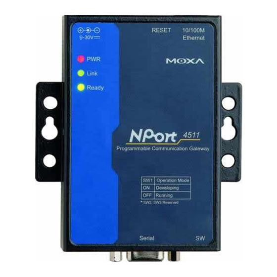
Front/Top/Rear Panel Views The reset button can be used in two different ways, so it requires further explanation. To use the reset button, press continuously for: 3 sec to erase the password After 3 sec, the ready LED will flash on/off every half second. Release the reset button at this time to erase password. -
Page 10: Schematic
Schematic LED Indicators NPort 4511’s top panel contains three LED indicators, as described in the following table. LED Name LED Color LED Function Power is on Power is off, or power error condition exists orange 10 Mbps Ethernet connection green... -
Page 11: Housing
To remove NPort 4511 from the DIN-Rail, simply reverse Steps 2 and 3 above by grasping the bottom of the NPort 4511 unit with both hands, and then using your fingers to pull down slightly on the bottom DIN-Rail mounts. This releases... -
Page 12: Wall Mount
6.5 mm in diameter, and the shafts should be no greater than 3 mm in diameter. Do not screw the screws in all the way—leave a space of about 2 mm to allow room for sliding the NPort 4511 unit’s ears between the wall and the screws. -
Page 13: Power Connection
Power Status Check Use the PWR LED on NPort 4511’s top panel to see if it is receiving power. A red light indicates that power is being received. The absence of a light indicates that power is not being received. -
Page 14: Ethernet Installation
For most applications, you will simply plug one end of your Ethernet cable into NPort 4511’s 10/100BaseTX port, and the other end into a Hub or Switch that is connected to your network. In this case, you should use a standard straight-through Ethernet cable, which is readily available from many commercial vendors. -
Page 15: Connecting To A Pc
In some cases, such as when configuring NPort 4511 or downloading software, you may find it convenient to connect NPort 4511 directly to your computer’s Ethernet card. To do this, you will need to use a cross-over Ethernet cable. This type of Ethernet cable is harder to find, although you can make your own cable by referring to the following cable wiring diagram. -
Page 16: Serial Port Installation
Serial Port Installation In this chapter, we give the DB9 Female Connector Pinouts. The following topics are discussed: RS-232 Pinouts and Loopback Tester RS-422/485 Pinouts and RS-422 Loopback Tester Mini Adapter RS-232 Pinouts and Loopback Tester... -
Page 17: Rs-422/485 Pinouts And Rs-422 Loopback Tester
RS-422/485 Pinouts and RS-422 Loopback Tester... -
Page 18: Loopback Header
In order to make it easier for our customers to attach NPort 4511 to any serial device, a DB9 (male) to DB9 (male) mini null-modem adapter is included as a standard accessory with NPort 4511. -
Page 19: Terminal Block
Terminal Block To ease wiring concerns, NPort 4511 now comes with a 9-pin terminal block as a standard accessory, as shown below. The terminal block has a Male DB9 connector that can be used in conjunction with the mini adapter to connect directly to NPort 4511 (note that the terminal block is wired pin-to-pin). -
Page 20: Operation Mode Settings
Developing Mode Running Mode DIP Switch Settings The top panel of NPort 4511 contains the following table, which shows how DIP switch 1 (SW1) is used to select NPort 4511’s operation mode. SW1 is located on NPort 4511’s front panel. -
Page 21: Operation Mode Introduction
Operation Mode Introduction NPort 4511’s two Operation Modes are described in the following subsections. Developing Mode Developing Mode is used when configuring NPort 4511 and when developing and/or downloading a program. The following functions are available when NPort 4511 is in Developing Mode: Run/Stop NPort 4511’s program manually for testing and debugging... -
Page 22: Declaration Of Conformity
Declaration of Conformity Manufacturer Moxa Technologies Co., Ltd. Manufacturer’s Address Fl.4, No.135, Lane 235, Pao-Chiao Rd., Shing Tien City, Taipei, Taiwan, R.O.C. The manufacturer declares that this product conforms to the following standards: Product Name Programmable Communication Gateway Model Number... -
Page 23: Return Procedure
Return Procedure For product repair, exchange, or refund, the customer must: ♦ Provide evidence of original purchase. ♦ Obtain a Product Return Agreement (PRA) from the sales representative or dealer. ♦ Fill out the Problem Report Form (PRF). Include as much detail as possible for a shorter product repair time. -
Page 24: Problem Report Form
Programmable Communication Gateway Customer name: Company: Tel: Fax: Email: Date: 1. Moxa Product: NPort 4511 (1 RS-232/422/485 port) 2. Interface: RS-232 RS-422 RS-485 (ADDC) 3. Serial Number: __________________________ 4. NPort Firmware Version: __________________ 5. NPort Manager Version: ___________________ 6. PC Host:...
Need help?
Do you have a question about the NPort 4511 and is the answer not in the manual?
Questions and answers