Advertisement
Quick Links
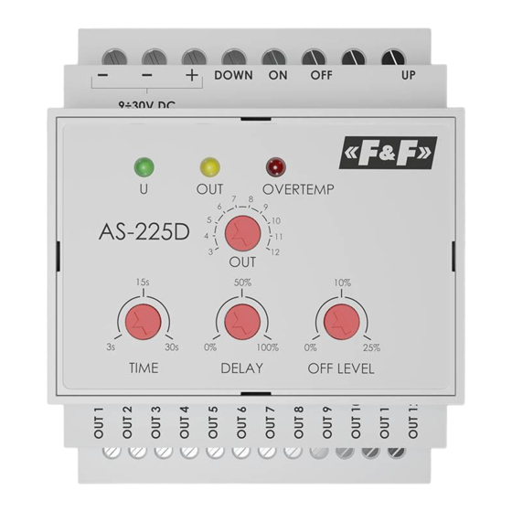
AS-225D
12-channel
cascade controller
Do not dispose of this device in the trash along with other waste!
According to the Law on Waste, electro coming from households free of charge and can
give any amount to up to that end point of collec� on, as well as to store the occasion of
the purchase of new equipment (in accordance with the principle of old-for-new, regard-
less of brand). Electro thrown in the trash or abandoned in nature, pose a threat to the
environment and human health.
Purpose
The AS-225D controller is designed for cascade control of
12÷24 V staircase lighting, which allows to achieve the effect of
light following a person walking up or down the stairs.
Features
» Control of cascading multi-point lighting system;
» The ability to set the number of controlled light points (from
3 to 12);
» The ability to connect controllers in series to increase the num-
ber of controlled circuits;
» Additional control inputs:
̶ permanent light switching (for example during houseworks);
̶ light switching lock (for example brightness sensor signal);
» Control of light using a variety of setters including bell buttons,
motion sensors, optical barriers, pressure sensors, etc.
» Adjustable "soft start" feature – soft brightening and dimming
of lighting;
F&F Filipowski sp. j.
Konstantynowska 79/81, 95-200 Pabianice, POLAND
phone/fax (+48 42) 215 23 83 / (+48 42) 227 09 71
www.fif.com.pl; e-mail: biuro@fif.com.pl
- 1 -
Advertisement

Related Manuals for F&F AS-225D


Summary of Contents for F&F AS-225D
- Page 1 Electro thrown in the trash or abandoned in nature, pose a threat to the environment and human health. Purpose The AS-225D controller is designed for cascade control of 12÷24 V staircase lighting, which allows to achieve the effect of light following a person walking up or down the stairs.
-
Page 2: Operator Panel
» Installation of the controller on a DIN rail; » Built-in thermal protection. Operator panel The operating parameters of the AS-225D controller are set using the knobs on the front of the unit. The operating status is indicated by LEDs,... - Page 3 Func- Description tion Set the number of controlled output circuits. Setting range from 3 to 12. The first controlled circuit is always OUT 1 (when the DOWN button is pressed, the cascade will start from OUT 1). The setting of this knob determines which controlled circuit will be the last So if, for example OUT is set to 9, the last output to be controlled will be OUT 9 (when the UP button is pressed the cascade will...
- Page 4 LED signalling Controller power indication Output circuit power indication Signalling that the acceptable temperature inside the controller is exceeded. Warning! The AS-225D controller is equipped with thermal protection to prevent excessive OVER- overloading of the output circuits. TEMP If the temperature limit is exceeded, the pro- tection starts to work and limits the maximum brightness level first.
- Page 5 Identification of the fault reported by the OVERTEMP signal light State Description Normal operation Warning temperature exceeded, output Slow flashing brightness level limited to 1/2 the maximum value. Alarm temperature exceeded, output bright- Fast flashing ness level limited to 1/8 the maximum value. Persistent exceeding of the alarm temperatu- re, controller outputs turned off.
-
Page 6: Wiring Diagram
Wiring diagram - 6 -... -
Page 7: Description Of Terminals
Description of terminals Power supply of the controller Warning! Maintain proper power supply polarity as indicated on the – enclosure. Power Warning! If the simultaneous load of supply the controller exceeds 12÷16 A, con- nect two independent power wires "–" to the first and second terminal of the controller and lead them to the power supply unit. - Page 8 A short press on the UP button starts the cascade moving from top to bot- tom. The last circuit controlled will be switched on first, then the penultimate circuit, and so on until the first circuit OUT 1 is reached. Each of the outputs will be switched on for the time TIME Control (set by the knob on the controller).
- Page 9 Triggering of the OFF input (for example by an external brightness sensor) switches off all controlled output Control circuits. The lights in this mode are input completely off, regardless of the OFF LEVEL parameter setting. Operation of the DOWN and UP buttons in this mode is also disabled.
- Page 10 » the wires ("–") of all power supplies should be connected with each other and with the terminals ("–") of the AS-225D controller. Cascade control Starting another cascade while the previous one is run- ning will not interrupt the work of the first one, but will start the next one in the set direction.
- Page 11 When the number of controlled output circuits exceeds 12, the system can be expanded by connecting several AS-225D controllers in series. A sample wiring diagram is shown in the figure below. Example of cascade control According to the above scheme, any number of control- lers can be combined.
- Page 12 Technical data input power supply 9÷30 V DC output number of channels type transistor (OC – open collector) maximum load current (1 channel) maximum total load (12 channels) 24 A maximum voltage 30 V DC input type potential-free switch-on duration (1 channel) 3÷30 s delay in switching on the next channel 0÷switch-on duration...
-
Page 13: Warranty
Warranty The F&F products are covered by a warranty of the 24 months from the date of purchase. Effective only with proof of purchase. Contact your dealer or directly with us. CE declaration F&F Filipowski sp. j. declares that the device is in conformity with the essential requirements of the Electromagnetic Compatibility (EMC) Directive 2014/30/UE.
Need help?
Do you have a question about the AS-225D and is the answer not in the manual?
Questions and answers