Table of Contents
Advertisement
Quick Links
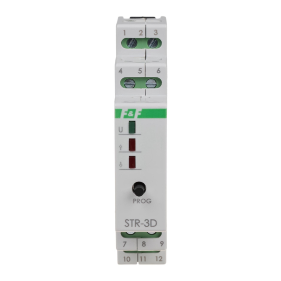
STR-3D
Roller blind controller
for 230 V AC
Do not dispose of this device in the trash along with other waste! According
to the Law on Waste, electro coming from households free of charge and
can give any amount to up to that end point of collec� on, as well as to sto-
re the occasion of the purchase of new equipment (in accordance with the
principle of old-for-new, regardless of brand). Electro thrown in the trash or
abandoned in nature, pose a threat to the environment and human health.
Purpose
STR-3D controller is designed to control roller blinds (�������)
or other objects (e.g. gates) that are driven with single-phase
alternating current electric motor with momentary switch (eg.
bell).
Functioning
The controller can operate as a stand-alone device (for opening/
closing of a single roller blind), but it is also possible to combine
Controllers into groups to central control multiple roller blinds.
Roller blind motor starts after momentary passing of the N si-
gnal to one of the control inputs. The motor activates for the
user-programmed time that allows to fully lift or lower the roller
blind. The controller power supply is indicated by a green LED.
Motor operation and direction of roller blinds movement is indi-
cated by the corresponding red ↓ or ↑ LED.
F&F Filipowski sp. j.
Konstantynowska 79/81, 95-200 Pabianice, POLAND
phone/fax (+48 42) 215 23 83 / (+48 42) 227 09 71
www.fif.com.pl; e-mail: biuro@fif.com.pl
- 1 -
Advertisement
Table of Contents

Related Manuals for F&F STR-3D


Summary of Contents for F&F STR-3D
- Page 1 Purpose STR-3D controller is designed to control roller blinds (�������) or other objects (e.g. gates) that are driven with single-phase alternating current electric motor with momentary switch (eg.
- Page 2 Roller blind can be stopped on the user-selected level (incomple- te opening or closing of the roller blind). Control Controller control inputs are divided into two groups: local con- trol and central control. ����� ������� Depending on how you connect the controller, it can operate in one or two local keys mode.
- Page 3 Memory of direction applies both to local and central control. For example, if the controller carries out a ������� �� command, then the next press of a local key will move the roller blind down. Memory of direction is not retained after a power fail- ure.
- Page 4 ������� ���� key can also close and lock the roller blind in the closed position. If the ������� ���� key is pressed and left in the �� position, the controller will close the roller blind and will not allow for its opening until the �������...
- Page 5 Scheduling time of activation Time of activation can be programmed upon the assumed time of roller blind operation or by activating the roller blind for the test run: Scheduling for the specified time 1. Press and hold (for approx. 4 s) the ���� key until the green U LED will begin to flash slowly.
- Page 6 If during the first 30 seconds of the learning mode (slow flashing of U LED) the time measuring will not start (the ���� key is pressed or the roller blind is activated from the local control input), the controller will exit the learn- ing mode.
- Page 7 Wiring diagram power supply 100÷265 V AC central control – �� ↑↑ direction central control – ���� ↓↓ direction local control – �� ↑ direction local control – ���� ↓ direction motor power supply – �� ↑ direction power supply input 230 V AC (L) motor power supply –...
- Page 8 Technical data power supply 100÷265 V AC maximum load current (AC-1/AC-3) 8 A/1.5 A power consumption staandby 0.15 W 0.6 W control triggered N level switch-on time (adjustable) 1 s÷15 min. power indication green LED operation and movement direction indication red 2×LED working temperature -25÷50°C...
Need help?
Do you have a question about the STR-3D and is the answer not in the manual?
Questions and answers