Table of Contents
Advertisement
Advertisement
Table of Contents

Related Manuals for Hemisphere GPS S320


Summary of Contents for Hemisphere GPS S320
- Page 1 S320 GNSS Survey Receiver™ User Guide Part No. 875-0281-000 Rev. C2...
- Page 2 If 400MHz FCC ID: NS909P30IC: 3143A-09P30 If your S320 is equipped with a 400 MHz radio you may be required to obtain a valid radio license for your jurisdiction. Only set the radio to the frequency and power you are licensed to use at your location.
- Page 3 This device complies with Part 15 of the FCC Rules. Operation is subject to the following two conditions: (1) this device may not cause harmful interference, and (2) this device must accept any interference received, including interference that may cause undesired operation. This equipment has been tested and found to comply with the limits for a Class B digital device, pursuant to Part 15 of FCC Rules.
- Page 4 Outback Steering Guide , PocketMax PC , PocketMax , PocketMax3 , R100 , R131 , R220 , R320 ® ® S320 , Satloc , the Satloc logo, SBX-4 , SLXMon , SureTrack , V101 , V102 , V103 , V111 , V113...
-
Page 5: Table Of Contents
Setting Up the Unit ................... 10 Chapter 3: Setup and Configuration ................11 Control Panel Overview ..................12 Powering the S320 On and Off ................. 14 Modes of Operation ..................14 Displaying Current Module Status ..............15 Changing Module Status ................... 16 Tilt Function Control .................. -
Page 6: Chapter 1: Introduction
Chapter 1: Introduction Product Overview and Features What’s Included S320 User Guide PN 875-0281-000 Rev C2... - Page 7 Chapter 1: Introduction Product Overview and Features The S320 is an integrated GNSS survey and mapping device for mobile data collection providing differential GPS (DGPS) accuracy in a rugged, all-in-one enclosure. Powered by Hemisphere GNSS’ powerful dual constellation and dual frequency Eclipse™ II OEM...
-
Page 8: What's Included
Chapter 1: Introduction What’s Included The S320 is available as a single unit or two units (base/rover setup). Figure 1-1 shows the parts included in the single unit kit and Table 1-1 lists the parts included in both kits. Figure 1-1: S320 single unit kit... -
Page 9: Chapter 2: Installation
Chapter 2: Installation Ports and Connections Installing/Connecting the S320 Attaching the Antenna Connecting to a Power Source Connecting to External Device Setting Up the Unit S320 User Guide PN 875-0281-000 Rev C2... -
Page 10: Ports And Connections
Data port Power port Antenna port Mounting hole Serial port Figure 2-1: S320 ports and connectors Table 2-1: S320 ports and connections Port What to connect Data port (ODU 9-pin) Data cable (Item H in Table 1-1 on page 3) -
Page 11: Installing/Connecting The S320
Chapter 2: Installation Installing/Connecting the S320 This section describes how to perform the following: Attaching the antenna Connecting to a power source) Setting up the unit) Attaching the Antenna You can attach the antenna in one of two ways: Attach the antenna directly to the antenna port on the bottom of the unit with the... -
Page 12: Connecting To A Power Source
Connecting to a Power Source The S320 power cable has a circular connector (2-pin ODU) at one end and two clamps at the other end (red clamp positive and black clamp negative). Figure 2-3 shows the power port pinout on the S320 and Table 2-2 shows the pin descriptions. -
Page 13: Connecting To External Devices
Chapter 2: Installation Connecting to External Devices You can connect the S320 to external devices via the serial and data ports on the bottom of the unit. Serial Port Pinout Specifications Figure 2-5 shows the DB9 serial port (female) pinout, while Table 2-3 shows the serial port pinout specifications. -
Page 14: Setting Up The Unit
See “Attaching the Antenna” for more information on attaching the antenna. Base setup Rover setup Figure 2-7: Typical base and rover setup S320 User Guide PN 875-0281-000 Rev C2... -
Page 15: Chapter 3: Setup And Configuration
Chapter 3: Setup and Configuration Control Panel Overview Powering the S320 On and Off Modes of Operation Displaying Current Module Status Changing Module Status Tilt Function Control Alarm/Buzzer Power and Battery Status/Charge Replacing/Swapping the Batteries Removing/Inserting the SD Card / SIM Card... -
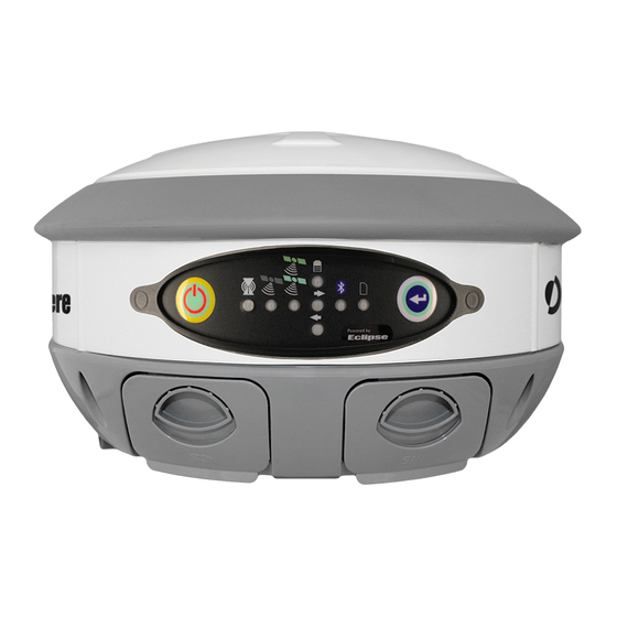
Page 16: Control Panel Overview
You operate the S320 using the control panel shown in Figure 3-1. Figure 3-1: S320 control panel The S320 beeps on any keypress. Table 3-1 describes each button and LED on the control panel. Table 3-1: S320 control panel items... - Page 17 Chapter 3: Setup and Configuration Table 3-1: S320 control panel items (continued) Diagram Name Description Item Select button Allows you to review module status or change the status (power (for Bluetooth/ on/off) of a module UHF/GSM/SD See “Displaying Current Module Status” and “Changing Module modules) Status”...
-
Page 18: Powering The S320 On And Off
Press and hold the Power button for 3 seconds (until you hear three beeps). Note: When you power on the S320 the LEDs go through a ‘heartbeat’ sequence (each LED lights up in succession); during this time the modules power up and the devices initialize. -
Page 19: Displaying Current Module Status
Chapter 3: Setup and Configuration Displaying Current Module Status The S320 allows you to quickly review the status of each module (UHF/GSM, mode of operation, Bluetooth, and SD card logging). To display current module status: Press the Select button. The external power status LED is red (the unit is displaying its current status) and the LED of each module will be either OFF (LED not illuminated, module powered off) or ON (LED illuminated, module powered on). -
Page 20: Changing Module Status
5 times to indicate a status change. changing) Repeat steps 2 and 3 for each remaining module (if desired). After a status change, the function of the LEDs return to normal mode S320 User Guide PN 875-0281-000 Rev C2... -
Page 21: Tilt Function Control
Chapter 3: Setup and Configuration Tilt Function Control The S320 includes tilt control functionality that allows you to level your unit using five of the LED indicators. When you activate tilt control you see the changes to the angle of the antenna in real time (similar to a level). -
Page 22: Alarm/Buzzer
Figure 3-2: No external power, right battery full, left battery not present Table 3-5 describes what the power/battery LED colors indicate. The S320 prioritizes power usage to use external power when available, regardless of the status of the internal batteries. -
Page 23: Replacing/Swapping The Batteries
Replacing/Swapping the Batteries If the S320 is off you can replace both batteries at one time. If you want to keep the unit running while replacing the batteries you must replace them one at a time to ensure the unit is receiving power from at least one battery. -
Page 24: Removing/Inserting The Sd Card / Sim Card
Caution: Use electrostatic discharge (ESD) protection by wearing an ESD strap that is attached to an earth ground, before inserting or removing the SIM card on the S320. If an ESD strap is not available then touch a metal object prior to accessing the SIM card holder. -
Page 25: Bluetooth Communication
If you have a Bluetooth-enabled device, such as a data collector, you can wirelessly communicate with the S320. When you attempt to connect the S320 to a Bluetooth-enabled device, such as a handheld data collector, the following S320 Bluetooth information appears on the device: HGPS S320 XXXXXX where “XXXXXX”... -
Page 26: Upgrading S320 Firmware
You can upgrade S320 firmware via serial port or SD card. Upgrading S320 Firmware via Serial Port Before you upgrade verify the S320 is powered off and, if you will not be using external power, both Li-ion batteries are fully charged and inserted into the S320. -
Page 27: Upgrading S320 Firmware Via Sd Card
In the Autoloader window click Exit. Upgrading S320 Firmware via SD Card Before you upgrade verify the S320 is powered off and, if you will not be using external power, both Li-ion batteries are fully charged and inserted into the S320. -
Page 28: Gsm Functionality
In that case the AT&T network can still be used. Tether the data collector in use with the S320 to a Wi-Fi hotspot to gain access to a data network using the “Data Collector Internet” option in the Carlson SurvCE software. In that case the user must have an external internet hotspot available, created with a mobile phone. -
Page 29: Configuring Sms Messaging
OFF (or to replace the current number in slot 1) send the following command: $JSMS,CONFIG,1,+19995551212,Service,OFF The status message state (ON or OFF) allows the S320 to send an SMS message back to the number to report information and events on the operation of the unit. -
Page 30: Restoring Factory Defaults
If you need to restore your factory defaults for any reason you can do this via the Control panel. To restore factory defaults: Press and hold the Power button for 10 to 20 seconds and release it while the GPS status and DGPS status LEDs are blinking. S320 User Guide PN 875-0281-000 Rev C2... -
Page 31: Appendix A: Troubleshooting
Appendix A: Troubleshooting S320 User Guide PN 875-0281-000 Rev C2... - Page 32 Appendix A: Troubleshooting Table A-1 provides troubleshooting tips for the S320. Table A-1: S320 troubleshooting Issue Possible Resolution External power is low Receiver fails to power Check charge on external battery and the fuse on the power cable, if applicable...
-
Page 33: Appendix B: Technical Specifications
Appendix B: Technical Specifications S320 User Guide PN 875-0281-000 Rev C2... - Page 34 Appendix B: Technical Specifications The following tables provide information on the technical specifications of the S320. Table B-1: GNSS receiver specifications Item Specification Receiver type Dual frequency GNSS Channels All in view GPS L1CA, L1P L2P, GLONASS L1CA, L1P L2CA, L2P...
- Page 35 1.51 kg (3.33 lb) Material Plastic Receive only, does not transmit this format. Depends on multipath environment, number of satellites in view, satellite geometry, and ionospheric activity. Depends also on baseline length. Requires an L-band subscription. S320 User Guide PN 875-0281-000 Rev C2...
- Page 36 DGPS position 13 control panel External power 13 overview 12 GPS position 13 power button 12 SD logging 13 Select button 13 UHF/GSM 13 data cable 3 mechanical specifications 31 data port 6 modes S320 User Guide PN 875-0281-000 Rev C2...
-
Page 37: Index
14 sending SMS message to approved number 26 module status serial port 6 upgrading firmware 22 changing 16 displaying 15 setting up the S320 10 mounting hole 6 SIM card inserting 20 removing 20 Single point mode 14 NTRIP 24... - Page 38 End User License Agreement IMPORTANT - This is an agreement (the "Agreement") between you, the end purchaser ("Licensee") and Hemisphere GNSS Inc. ("Hemisphere") which permits Licensee to use the Hemisphere software (the "Software") that accompanies this Agreement. This Software may be licensed on a standalone basis or may be embedded in a Product. Please read and ensure that you understand this Agreement before installing or using the Software Update or using a Product.
- Page 39 positioning and navigation accuracy obtainable with the Software as stated in the Product or Software documentation serves to provide only an estimate of achievable accuracy based on specifications provided by the US Department of Defense for GPS positioning and DGPS service provider performance specifications, where applicable. WARRANTY DISCLAIMER.
- Page 40 TERMINATION. Licensee may terminate this Agreement at any time without cause. Hemisphere may terminate this Agreement on 30 days notice to Licensee if Licensee fails to materially comply with each provision of this Agreement unless such default is cured within the 30 days.
-
Page 41: Warranty Notice
Warranty Notice COVERED PRODUCTS: This warranty covers all products manufactured by Hemisphere GNSS and purchased by the end purchaser (the "Products"), unless otherwise specifically and expressly agreed in writing by Hemisphere GNSS. LIMITED WARRANTY: Hemisphere GNSS warrants solely to the end purchaser of the Products, subject to the exclusions and procedures set forth below, that the Products sold to such end purchaser and its internal components shall be free, under normal use and maintenance, from defects in materials, and workmanship and will substantially conform to Hemisphere GNSS's applicable specifications for the Product, for a period of 12 months from delivery of such Product to such end purchaser (the ”Warranty Period”). - Page 42 8515 E. Anderson Drive Scottsdale, AZ 85255, USA Phone: 1 480 348 6380 Fax: 1 480 270 5070 precision@hemispheregnss .com www.hemispheregnss.com...
- Page 43 S320 GNSS Survey Receiver User Guide 875-0281-000 Revision: C2 April 21, 2017 Document Control: Art Escobedo Originator: Engineering Tech Manager Rodrigo Leandro Engineering: Sr. Director Engineering Lyle Geck Product Management: Product Manager Kishia Blackburn Configuration Management: Configuration Management Coordinator Michael Polinko...
Need help?
Do you have a question about the S320 and is the answer not in the manual?
Questions and answers