Siemens POLYMOBIL Plus Service Instructions Manual
Hide thumbs
Also See for POLYMOBIL Plus:
- Start-up instructions (24 pages) ,
- Start-up instructions (34 pages) ,
- Maintenance instruction (40 pages)
Table of Contents
Advertisement
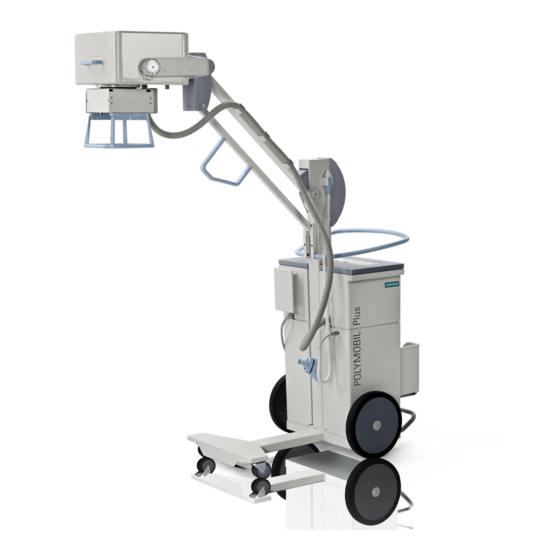
POLYMOBIL Plus
Service Instructions
From Serial-No. 10100
Print No.: SPR8-125.061.02.01.02
Replaces: n.a.
SP
© Siemens AG 2000
The reproduction, transmission or
use of this document or its contents
is not permitted without express
written authority. Offenders will be
liable for damages. All rights,
including rights created by patent
grant or registration of a utility
model
_or_ design,_are_
reserved.
English
Release Date:
01.00
Advertisement
Table of Contents

Related Manuals for Siemens POLYMOBIL Plus


Summary of Contents for Siemens POLYMOBIL Plus
- Page 1 POLYMOBIL Plus Service Instructions From Serial-No. 10100 © Siemens AG 2000 The reproduction, transmission or use of this document or its contents is not permitted without express written authority. Offenders will be liable for damages. All rights, including rights created by patent...
- Page 2 0 - 2 Revision Chapter Page Rev. Letzte Seite Kapitel POLYMOBIL Plus SPR8-125.061.02 Page 2 of 4 Siemens AG Rev. 01 01.00 TD SD 24 Medical Engineering...
-
Page 3: Table Of Contents
Setting the maximum filament inverter frequency ....5-12 Siemens AG SPR8-125.061.02 Page 3 of 4 POLYMOBIL Plus Medical Engineering Rev. 01 01.00 TD SD 24... - Page 4 Replacing the capacitor bank....... 6-6 7 ______ Changes to previous version ______________________________________7-1 Letzte Seite Kapitel POLYMOBIL Plus SPR8-125.061.02 Page 4 of 4 Siemens AG Rev. 01 01.00...
-
Page 5: Text Emphasis
The oscilloscope has to be connected to ground to perform mea- surements. A TEK video isolator and the trigger set have to be used when ground loops may distort the measurement results. Siemens AG SPR8-125.061.02 Page 1 of 4 POLYMOBIL Plus Medical Engineering Rev. 01 01.00 TD SD 24... -
Page 6: Safety Information And Protective Measures
CAUTION - the product-specific safety information in the document, - the safety information in RA0-000.012..in the Register of the POLYMOBIL Plus binder, as well as - the safety information contained in the ARTD Part 2. • Tests and adjustments that must be performed with radiation... - Page 7 This can cause life-threatening voltage to be present in the system even after a prolonged period of time. • Refer also to chapter "Replacing the capacitor bank". Siemens AG SPR8-125.061.02 Page 3 of 4 POLYMOBIL Plus Medical Engineering Rev. 01 01.00 TD SD 24...
-
Page 8: Replacing Damaged Or Missing Screws
1 - 4 Prerequisites • Connect the POLYMOBIL Plus only to a line voltage supply (line voltage receptacle) that complies with the requirements of VDE 0107, or corresponds to the local national regulations. • Disconnect the POLYMOBIL Plus at the line voltage OFF switch on the operating console and disconnect the line voltage plug prior to any service work. -
Page 9: Preparation
The capacitor bank can still be charged. Do not attempt to work on the system while this condition exists. • For details see chapter "Prerequisites". Siemens AG SPR8-125.061.02 Page 1 of 8 POLYMOBIL Plus Medical Engineering Rev. 01 01.00 TD SD 24... - Page 10 To check the assemblies, remove the upper covers, the handles and the lower front cover of the switchbox. Proceed as follows: • Switch POLYMOBIL Plus OFF and disconnect the line voltage plug. • Remove the 4 Allen screws (1/Fig.2) in the handle and remove the handle (refer to Fig.2 and Fig.3).
- Page 11 Remove the four screws of the top housing (4/Fig.5) • To stay clear of the exposure guide holder, tilt the housing forward and lift it up to remove it. Siemens AG SPR8-125.061.02 Page 3 of 8 POLYMOBIL Plus Medical Engineering Rev. 01 01.00 TD SD 24...
-
Page 12: Position And Function Of The Leds, Fuses, Test Points And Potentiometers
Max. main inverter frequency Adjustment/setting of filament heating circuit Nominal filament current (standby and ZB), nominal tube current (exposure) Set at the factory - Do not change! Nominal kV value POLYMOBIL Plus SPR8-125.061.02 Page 4 of 8 Siemens AG Rev. 01 01.00... -
Page 13: D925 Rotating Anode Starter, Filament Inverter, On/Off Switching Circuit
Auxiliary voltage +12.5 V 3.2 AF Line voltage for anode starter 1.0 AT Line voltage for filament circuit 10 AT Power 10 AT Power Siemens AG SPR8-125.061.02 Page 5 of 8 POLYMOBIL Plus Medical Engineering Rev. 01 01.00 TD SD 24... -
Page 14: U1 Power Supply Unit 5 V ± 5% / 15 V ± 10
U1 power supply unit 5 V ± 5% / 15 V ± 10 % Fuse: 2 A T U2 power supply unit 12.5 V ± 10 % Fuse: 5 A T POLYMOBIL Plus SPR8-125.061.02 Page 6 of 8 Siemens AG Rev. -
Page 15: D950 Capacitor Charging Circuit
Capacitor charging voltage for C1 - C10 80AF Capacitor voltage for inverter 20AF Charging voltage for capacitor bank Test points: -VCC, +VCC Capacitor voltage Siemens AG SPR8-125.061.02 Page 7 of 8 POLYMOBIL Plus Medical Engineering Rev. 01 01.00 TD SD 24... -
Page 16: Status Of The Led's (Optimum Condition)
2 - 8 Checking the assemblies Status of the LED’s (optimum condition) a) POLYMOBIL Plus OFF, line voltage plug connected: D925: +12 V D950: 450 Vcc (V30) glows for 10 minutes following shutdown D970: all LED’s glows for 10 minutes following shutdown... -
Page 17: Error Messages
Err 21 Vfil > Vmax during prep Maximum filament heating exceeded during preparation Err 22 Maximum prep time Max. preparation time exceeded Siemens AG SPR8-125.061.02 Page 1 of 4 POLYMOBIL Plus Medical Engineering Rev. 01 01.00 TD SD 24... -
Page 18: Troubleshooting After Error Messages
- Plug-in connection on D900 in the single tank generator ok? ≠ ≠ Err 7 0 (rotating anode speed - Error on D915 or D925. POLYMOBIL Plus SPR8-125.061.02 Page 2 of 4 Siemens AG Rev. 01 01.00 TD SD 24... - Page 19 - Error in the measurement circuit on D915? - Main inverter frequency too low? - Defect in the main inverter D960? < Err 15 - Check the filament circuit. Siemens AG SPR8-125.061.02 Page 3 of 4 POLYMOBIL Plus Medical Engineering Rev. 01 01.00 TD SD 24...
- Page 20 EPROM checksum - EPROM defective. Err 96 kVnom failure (hardware error , refer also to Err 5) Err 97 mAnom failure (hardware error, refer also to Err 6) POLYMOBIL Plus SPR8-125.061.02 Page 4 of 4 Siemens AG Rev. 01 01.00...
- Page 21 Setting of the mAs values in "Pr. 5" and "Pr. 6". Lamp switch Activating or quitting the current program To quit the service mode, switch the POLYMOBIL Plus off/on or press the Reset button SW 2 (2/Fig.1). Siemens AG SPR8-125.061.02...
-
Page 22: Service Programs Available
"FIL 3" appears on the display after starting the service program. Press S27. Filament boosts; "FIL 5" appears on the display. NOTICE There is no radiation present during these service programs. POLYMOBIL Plus SPR8-125.061.02 Page 2 of 2 Siemens AG Rev. 01 01.00... -
Page 23: Line Voltage
Ground at "GND" 10 ms/Div Trigger external at TP "TRG" • Set 90 kV and 10 mAs at the POLYMOBIL Plus and release an exposure. The oscillogram should correspond to the one shown in Fig. 1. Fig. 1 Siemens AG SPR8-125.061.02... -
Page 24: Capacitor Charging Circuit
Ground at "GND" 20 µs/Div • After switch on the following oscillogram can be measured: Fig. 2 The capacitor charging frequency is 25 kHz and cannot be adjusted. POLYMOBIL Plus SPR8-125.061.02 Page 2 of 20 Siemens AG Rev. 01 01.00... -
Page 25: Capacitor Charging Current
U ) of the capacitor bank. Fig. 3 shows the charging current in standby, i. e. when the C-bank is charged. Siemens AG SPR8-125.061.02 Page 3 of 20 POLYMOBIL Plus Medical Engineering Rev. 01 01.00 TD SD 24... -
Page 26: Capacitor Voltage (Uc) And Charging Time
CAUTION You can measure the capacitor voltage at TP "VC" only if POLYMOBIL Plus is switched on. The charging time depends upon the residual charge of the capacitor bank and on the available line voltage, e.g. with 230 V the max. charging time is about 15 s. -
Page 27: Rotating Anode Starter
CH1 D915 test point "I2" (1 V 0.25 A) 10 ms /Div Fig. 5 NOTICE The currents are correspondingly lower at 100V line voltage. Siemens AG SPR8-125.061.02 Page 5 of 20 POLYMOBIL Plus Medical Engineering Rev. 01 01.00 TD SD 24... -
Page 28: Brakes
0.25 A) CH1 D915 test point "I2" (1 V 0.25 A) 10 ms /Div Fig. 6 NOTICE The currents are correspondingly lower at 100V line voltage. POLYMOBIL Plus SPR8-125.061.02 Page 6 of 20 Siemens AG Rev. 01 01.00 TD SD 24... -
Page 29: Kv Control
µ µ Tolerance: -1.5 s /+1.5 = 55.5 Fig. 7 • Setting the maximum main inverter frequency with potentiometer P4 on D 915. Siemens AG SPR8-125.061.02 Page 7 of 20 POLYMOBIL Plus Medical Engineering Rev. 01 01.00 TD SD 24... -
Page 30: Measuring The Oscillating Current
DC voltage is present. Check the actual charge with the DVM. • Switch OFF POLYMOBIL Plus and wait until the capacitor voltage has dropped to a value < 10 V. • Disconnect the cable from the inverter to capacitor C1 and push the cable through the current transformer 50 A : 50 mA (with a parallel resistor of 10 ohms) and connect the cable again. -
Page 31: Measuring The Kvact And Kvnom
Measuring the kVact and kVnom • Connect the oscilloscope to D915 at TP "KV", "KVS" and "GND". • Set 60 KV, 10 mAs on POLYMOBIL Plus and release exposure. • The oscillogram must appear like the one in Fig. 9. •... -
Page 32: Error In The Kvact Acquisition
Exposure data: 102 KV 10 mAs KVact: CH1: D915 test point "KV" Itube: CH2: D915 test point "JR" CH3: D915 test point "KVM" 1 ms /Div POLYMOBIL Plus SPR8-125.061.02 Page 10 of 20 Siemens AG Rev. 01 01.00 TD SD 24... -
Page 33: Testing The Filament Circuit
Connect the oscilloscope to D915 at TP "CAL", "I" and "GND". Fig. 11 Filament inverter frequency CH1: D915 test point "CAL" Filament current CH2: D915 test point "I" Siemens AG SPR8-125.061.02 Page 11 of 20 POLYMOBIL Plus Medical Engineering Rev. 01 01.00 TD SD 24... -
Page 34: Setting The Maximum Filament Inverter Frequency
Remove fuse F6 on D925. • Connect the oscilloscope to D915 at TP "CAL" and "GND". • Switch POLYMOBIL Plus ON (Err 03 is blinking). The oscillogram must appear like the one in Fig. 12. CH1: D915 test point "CAL" 20 µs /Div Fig. -
Page 35: Measuring The Filament Nominal Value
• Connect the oscilloscope to D915 at TP "JR", "IH" and "GND". • Set 60 kV, 10 mAs on POLYMOBIL Plus and release an exposure. The oscillogram must appear like the one in Fig. 13. Fig. 13 Actual tube current valueCH1: D915 test point "JR"... - Page 36 5 - 14 Measurements Tek Stop: Single Seq 2.50kS/s 1.00V M20.0ms 1.56V 500mV Standby heating too high Fig. 14 Standby heating too low Fig. 15 POLYMOBIL Plus SPR8-125.061.02 Page 14 of 20 Siemens AG Rev. 01 01.00 TD SD 24 Medical Engineering...
-
Page 37: Testing And Setting The Mas Counter
Pull out the mAs jumper on D900 and connect the mAs meter. • Set 70 kV, 80 mAs on POLYMOBIL Plus and release exposure. If the value displayed on the mAs meter does not coincide with the value set on POLYMOBIL Plus, adjust the mAs counter with P1 on D915. -
Page 38: Coincidence Of Light And Radiation Fields
Release an exposure (60 kV, 10 mAs) and develop the film. • Log the following data on the developed film using a water-resistant felt-tip pen. - SID setting - Film size - Radiation field size POLYMOBIL Plus SPR8-125.061.02 Page 16 of 20 Siemens AG Rev. 01 01.00... - Page 39 • The deviations in length (total Y) as well as the deviations in width (total X) must be smaller than 1.6 cm respectively. Siemens AG SPR8-125.061.02 Page 17 of 20 POLYMOBIL Plus Medical Engineering Rev. 01 01.00 TD SD 24...
- Page 40 After adjusting the collimator, tighten the screws again (arrow / Fig.18/19). • Repeat the test and readjust the collimator until the light and radiation fields are within the acceptable tolerance (< 1.6 cm). POLYMOBIL Plus SPR8-125.061.02 Page 18 of 20 Siemens AG Rev.
-
Page 41: Testing And Readjusting The Counterbalance
Adjust the spring tension in such a way, that there is a balance when the C-arm is in a vertical position, i.e. that equal force is required to lift and lower the tube assembly. Siemens AG SPR8-125.061.02 Page 19 of 20 POLYMOBIL Plus Medical Engineering Rev. 01 01.00 TD SD 24... - Page 42 5 - 20 Measurements This page intentionally left blank. POLYMOBIL Plus SPR8-125.061.02 Page 20 of 20 Siemens AG Rev. 01 01.00 TD SD 24 Medical Engineering...
-
Page 43: Replacing The Single Tank Generator
Replacing important components 6 - 1 NOTICE To repair paint chips, the POLYMOBIL Plus colors can be ordered in spray cans: "white" spray paint 84 27 734 RE999 "ergo gray" spray paint 84 27 742 RE999 "medical blue" spray paint (in preperation) Fig. - Page 44 Set the tube current (refer to "Setting the tube current for the exposure", pp 5-12). • Check the coincidence of the light and radiation fields and adjust, if necessary (refer to "Coincidence of light and radiation fields", pp 5-15) POLYMOBIL Plus SPR8-125.061.02 Page 2 of 8 Siemens AG Rev.
-
Page 45: Replacing The Collimator
Check the coincidence of the light and radiation fields and adjust, if required. (Refer to “Coincidence of light and radiation field”, page 5-15.) Siemens AG SPR8-125.061.02 Page 3 of 8 POLYMOBIL Plus Medical Engineering Rev. 01 01.00 TD SD 24... -
Page 46: Replacing The Lamp For The Localizer
• Check the function of the light localizer lamp. • Check the considence of light and radiation fields (see "Considence of light and radiation fields" in chapter 5). POLYMOBIL Plus SPR8-125.061.02 Page 4 of 8 Siemens AG Rev. 01 01.00... -
Page 47: Replacing The Steering Caster
Align the threaded holes on the new caster. • Install in the reverse sequence. • Test the pedal positions (Refer to Operating Instructions). Siemens AG SPR8-125.061.02 Page 5 of 8 POLYMOBIL Plus Medical Engineering Rev. 01 01.00 TD SD 24... -
Page 48: Replacing The Capacitor Bank
Electric shock ! • The capacitor bank can still be charged. Do not attempt to work on the system while this condition exists. • For details see chapter "Prerequisites". POLYMOBIL Plus SPR8-125.061.02 Page 6 of 8 Siemens AG Rev. 01 01.00... - Page 49 If a fuse on D970 is defective, high voltage may still be present at the affected capacitor. In this case, discharge the affected capacitor with the discharging resistor R5 (5/Fig. 11) . Siemens AG SPR8-125.061.02 Page 7 of 8 POLYMOBIL Plus Medical Engineering Rev. 01 01.00 TD SD 24...
- Page 50 Check the capacitor voltage (Uc) and the charging time (refer to "Capacitor voltage (Uc) and charging time ", page 5-3) SMS Iselin / O’Donnell TD SD 24 / Am-Ende TD SD 24 / Groß POLYMOBIL Plus SPR8-125.061.02 Page 8 of 8 Siemens AG Rev. 01 01.00...
Need help?
Do you have a question about the POLYMOBIL Plus and is the answer not in the manual?
Questions and answers