Advertisement
Quick Links
F&F Filipowski sp. j.
Konstantynowska 79/81 95-200 Pabianice
tel/fax +48 42 2152383; 2270971 POLAND
http:/www.fif.com.pl e-mail: fif@fif.com.pl
BISTABLE RELAY
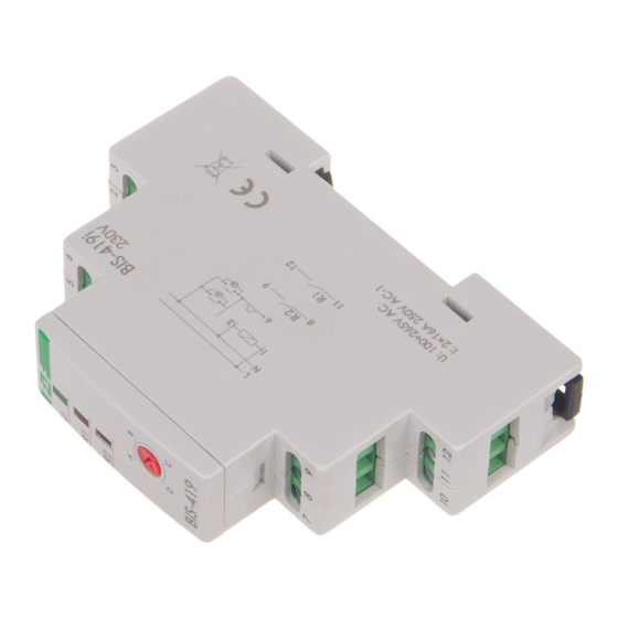
BIS-419-LED
sequential
230V
4-function
WARRANTY. The F&F products are
covered by a warranty of the 24 months
from the date of purchase. Effective only
with proof of purchase. Contact your
dealeror directly with us. More infor-
mation how to make a compliant can be
found on the website:
5
9 0 8 3 1 2
5 9 8 4 9 7
www.fif.com.pl/reklamacje
Do not dispose of this device to a garbage bin with other unsorted waste!
In accordance with the Waste Electrical and Electronic Equipment Act
any household electro-waste can be turned in free of charge and in any
quantity to a collection point established for this purpose, as well as to the
store in the event of purchasing new equipment (as per the old for new rule,
regardless of brand). Electro-waste thrown in the garbage bin or abandoned
in the bosom of nature pose a threat to the environment and human health.
Purpose
Electronic bistable pulse relay switch that turns on or off lights or other equip-
ment from several different points with the parallel connected momentary
(bell) control switches.
BIS-419 relay has two switching sections and allows for switching of two
lightning circuits or others receivers from several different points and in
accordance with the preselected sequence.
Operation
The relay power supply is indicated by a green LED U. Sequential relay has two
separate outputs: R1 and R2. Contact status (closed/open) is forced sequen-
tially in accordance with a predetermined program. Contacts switch to ano-
ther state after subsequent pulse from control button. R1 and R2 contact
activation is indicated by the relevant R1 and R2 red LED. After a power failure,
contact state is reset. When the power is back on, the relay starts from the
sequence number 0.
- 1 -
Installation
1. Disconnect the power supply.
2. Mount relay on the rail in the connection box.
3. Connect the power supply cables to terminals 1-3 according to the selected
mode of relay control (control pulse L or N).
4. Connect parallel connected momentary switches to the terminal 6 and to
the cable, to which the terminal 3 is connected.
5. Powered receiver of section R1 connect in series to terminals 11-12.
Powered receiver of section R2 connect in series to terminals 8-9.
6. Set the desired program (sequence) with a knob at the front casing of the
relay.
Relay version "LED" is to pin adapted to cooperate with the receivers with high
starting current, such as LED fluorescent lamps, ESL fluorescent lamps,
electronic transformers, discharge lamps, etc.
Note!
BIS-419-LED 230 V can be used with backlit buttons (ΣI<5mA).
Technical data
power supply
100÷265
contact
2×separated (1×NO)
load current (AC-1)
<16A (16A/20ms)
control pulse
100÷265
V AC <20mA
max current control buttons
activation delay
0,1÷0,2s
power indicator
green LED
activation indicator
2× red
power consumption
standby
on
working temperature
- ÷50°C
25
terminal
2.5mm screw terminals
²
tightening torque
dimensions
1 module (18mm)
mounting
on TH-35 rail
ingress protection
- 2 -
Table of power
incadescent
halogen
fluorescent
1250W
1000W
2000W
These data are indicative and will heavily depend on the design of a specific
receiver (that is especially important for LED bulbs, energy-saving lamps,
electronic transformers and pulse power supply units), switching frequency
and operating conditions.
For more information visit: fif.com.pl
Wiring diagram
control pulse: N
L
L
N
N
V AC
1
3
Σ mA
5
6
R2
LED
8
9
0. W
15
0. W
9
R1
12
11
11
0.4Nm
I 20
P
- 3 -
Example of relay installation with two lightning sections in „zero" (N) control
system.
energy-saving
LED
500W
250W
N
L
R2
control pulse: L
1
3
6
R2
8
9
R1
12
D150224
1
2
3
4
5
6
R1
U
R1
R2
A
B
D
C
BIS-419
7
8
9
10
11
12
- 4 -
Advertisement


Need help?
Do you have a question about the BIS-419-LED and is the answer not in the manual?
Questions and answers