Table of Contents
Advertisement
Quick Links
Advertisement
Table of Contents

Subscribe to Our Youtube Channel
Related Manuals for Lincoln Electric Computer Weld Technology DMC II


Summary of Contents for Lincoln Electric Computer Weld Technology DMC II
- Page 1 10702 Old Bammel N Houston Rd. Computer Weld Technology Houston, TX 77086 A Lincoln Electric Brand Phone: (713) 462-2118 Fax: (713) 462-2503 Email: cwt@cweldtech.com DMC II DC DRIVE MOTOR CONTROL Operation / Installation Manual Manual Part Number: S8M5021 April 24, 2019...
- Page 3 SAFETY PRECAUTIONS – READ BEFORE USING Welding is not particularly hazardous when certain safety practices are followed. Everyone using this equipment should be thoroughly trained in safe welding practices. Failure to observe safe practices may cause serious injury. Handling welding torches presents no danger if the appropriate safety regulations are strictly adhered to. For example: •...
- Page 4 Do not weld or cut on coated metals, such as galvanized, lead, or cadmium plated steel, unless • the coating is removed from the weld area, the area is well ventilated, and while wearing an air supplied respirator. The coatings and any metals containing these elements can give off toxic fumes if welded.
- Page 5 Follow requirements in OSHA 1910.252 (a) (2) (iv) and NFPA 51B for hot work and have a fire • watcher and extinguisher nearby. Read and understand the Safety Data Sheets (SDSs) and the manufacturer’s instructions for • adhesives, coatings, cleaners, consumables, coolants, degreasers, fluxes and metals. Electric Shock Touching live electrical parts can cause fatal shocks or severe burns.
- Page 6 Cylinders Compressed gas cylinders contain gas under high pressure. If damaged, a cylinder can explode. Since gas cylinders are normally part of the welding process, be sure to treat them carefully. Protect compressed gas cylinders from excessive heat, mechanical shocks, physical damage, •...
- Page 7 Additional Safety Warnings for Installation, Operation and Maintenance READ INSTRUCTIONS Read and follow all labels and the Owner’s Manual carefully before • installing, operating, or servicing the unit. Read the safety information at the beginning of the manual and each section. •...
- Page 8 About Implanted Medical Devices: Implanted Medical Device wearers should consult their doctor and the device manufacturer before performing or going near arc welding, spot welding, gouging, plasma arc cutting, or induction heating operations. If cleared by your doctor, then following the above procedures is recommended. Safety Standards •...
-
Page 9: Table Of Contents
Table of Contents GENERAL DESCRIPTION .................... 1 FUNCTIONAL DESCRIPTION ........................1 INSTALLATION ......................3 LOCATION ..............................3 OPERATION ........................7 THEORY OF OPERATION .........................7 CONTROL CALIBRATION ..........................7 MODBUS MEMORY MAP ..................... 9 GENERAL DESCRIPTION ..........................9 SUPPORTED MODBUS COMMANDS ......................9 MEMORY MAP FOR COILS (MODBUS COMMAND 01,05,15) ..............9 COIL DEFINITIONS AND OPERATION .................... -
Page 11: General Description
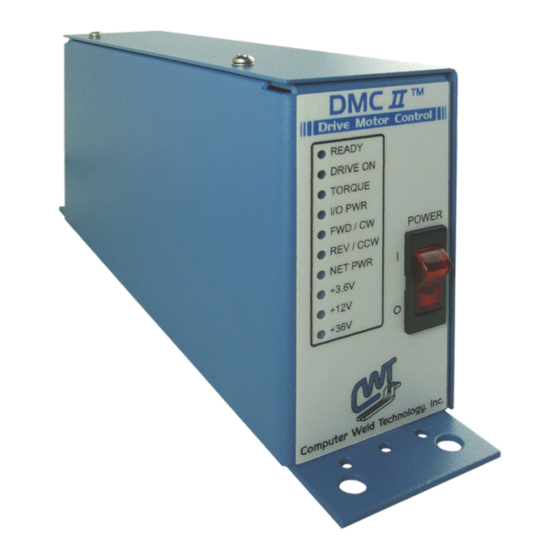
GENERAL DESCRIPTION FUNCTIONAL DESCRIPTION The DMC II Motor Controller is a PWM motor speed controller using an embedded micro controller to provide motor speed regulation and torque compensation. There are two version of the DMC II controller. The DMC II-LV has a 24 VDC @ 6.5amps output and the DMC II-HV has a 100 VDC @ 2.8 amps output. - Page 12 NET PWR – Illuminates when power is applied to the isolate RS-485 serial Com port. • • +3.8V – Illuminates when the 3.6 volt power supply is active. • +12V – Illuminates when the +12 volt power supply is active +36V –...
-
Page 13: Installation
INSTALLATION LOCATION The DMC II controller should be located near the drive motor it is controlling. The maximum motor drive cable length is 75 ft. Mount the DMC II controller in a location that allows easy access to the front and rear panel. - Page 14 Connect power cable to suitable 115 VAC power outlet. Connect motor control cable to MOTOR connector on rear of enclosure. Connect remote I/O cable (S3W5219) to I/O connector on rear of enclosure. DC Motor Connector Pin-Out Several cables are available from the factory, which and can be used for connecting a DC drive motor to the DMC II™.
- Page 15 The following is the connection diagram for a 15 VDC encoder: ENC +15VDC ENC PULSE 15 volt Encoder ENC COM Fig 2-4 15-volt TTL encoder connection Motor Connection The DMC-HV can be used with a permanent magnet, or shunt field motors with an armature rating of 90 –...
- Page 16 Remote I/O Connector Pin-Out The DMC II is controlled via the REMOTE I/O connector. The control has two (2) 24 VDC inputs for motor direction control, a 0-10 vdc input for speed control and a 24 VDC output. The following is the pin-out for the REMOTE I/O connector: FUNCTIONAL DEPWMIPTION +24 vdc output @ 100ma output...
-
Page 17: Operation
OPERATION Theory of Operation The DMC II is PWM motor speed controller. The control uses an embedded micro-controller to provide line synchronization, phased back EMF sampling and direction control logic with anti-plug motor reversing. The phased EMF sample provides precise back EMF sample for improve motor speed regulation. - Page 18 Disable the forward direction input. Turn the power off and reinstall the DMC cover.
-
Page 19: Modbus Memory Map
MODBUS MEMORY MAP General Description This document provides the basic Modbus memory map and command structure for the DMC II RS-485 communications port. The DMC II supports the Modbus Protocol as specified in the Modicon Technical publications “Modbus Protocol” (intr7.html). The DMC II control does not support the Broadcast mode. -
Page 20: Coil Definitions And Operation
Coil Definitions and Operation The DMC II has 16 simulated coils. These coils are used as internal bit flags to perform specific functions. The DMC II supports both single and group force coil commands. Refer to Section 4.3 for summary of the Coil functions. Memory Map for Holding Register (Modbus Command 03, 06, 16) The following is the Register definitions address 0-19: REGISTER... -
Page 21: Memory Map For Slave Id (Modbus Command 17)
Modifying the Holding Register[14 – 20] values may result in a catastrophic failure of the controller Memory Map for Slave ID (Modbus Command 17) The following is a summary of the Report Slave ID and Status (Code 17) Response Data fields: Byte Contents Sensor ID Number =10 Hex (Version 1, Rev0) -
Page 22: Appendix Asystem Drawings
APPENDIX A SYSTEM DRAWINGS DMC II Low Voltage Enclosure Assembly 110VAC - P/N: S3A5160... - Page 23 ITEM PART NO DESCRIPTION S3W5216 Harness, Power Supply S3E5108 Enclosure S3E5109 Cover S3E5110 Overlay, Front S3E5111 Overlay, Rear S3W5159 Cable, 110VAC Power S3W5160 Harness, Power Switch S3W5162 Harness, Motor/Encoder S3W5163 Harness, I/O S3W5164 Harness, Comm S5A5076 PCB Assembly, DMC-2 36V Drive X3P5841 Connector, Housing 8 Circuit X3P5875...
-
Page 24: Dmc Ii Low Voltage Enclosure Assembly 220Vac - P/N: S3A5169
DMC II Low Voltage Enclosure Assembly 220VAC - P/N: S3A5169... - Page 25 ITEM PART NO DESCRIPTION S3W5216 Harness, Power Supply S3E5108 Enclosure S3E5109 Cover S3E5110 Overlay, Front S3E5111 Overlay, Rear S3W5171 Cable, 220VAC European Power S3W5160 Harness, Power Switch S3W5162 Harness, Motor/Encoder S3W5163 Harness, I/O S3W5164 Harness, Comm S5A5076 PCB Assembly, DMC-2 36V Drive X3P5841 Connector, Housing 8 Circuit X3P5875...
-
Page 26: Dmc Ii High Voltage Enclosure Assembly 110Vac - P/N: S3A5161
DMC II High Voltage Enclosure Assembly 110VAC - P/N: S3A5161... - Page 27 ITEM PART NO DESCRIPTION S3E5108 Enclosure S3E5109 Cover S3E5110 Overlay, Front S3E5111 Overlay, Rear S3W5159 Cable, 110VAC Power S3W5160 Harness, Power Switch S3W5162 Harness, Motor S3W5163 Harness, I/O S3W5164 Harness, Comm S5A5086 PCB Assembly, DMC-2 HV2 X3P5841 Connector, Housing 8 Circuit X3P5875 Connector, Housing 3 Circuit X3S5078...
-
Page 28: Miller A1D4 Motor Control Cable - P/N: S3W5059
Miller A1D4 Motor Control Cable – P/N: S3W5059 ITEM PART NO DESCRIPTION X3P5586 Connector, Plug 12 Circuit Male X3P5589 Clamp, Cable X3P5505 Boot, Cable Clamp X3P5516 Connector, Plug 14 Circuit Female X3P0303 Terminal, Socket 22 awg X3P0302 Terminal, Socket 18 awg X3Z5054 Clamp, Cable X3W5020... -
Page 29: Standard W/O Tach Motor Control Cable - P/N: S3W5060
Standard w/o Tach Motor Control Cable – P/N: S3W5060 ITEM PART NO DESCRIPTION X3P5586 Connector, Plug 12 Circuit Male X3P5589 Clamp, Cable X3P5505 Boot, Cable Clamp X3W5079 Cable, 4 Conductor 16 awg DESCRIPTION WIRE TYPE FROM ARM+ 16 AWG RED ITEM 1 PIN M ARM- 16 AWG BLACK... -
Page 30: Lincoln Na5 Motor Control Cable - P/N: S3W5072
Lincoln NA5 Motor Control Cable – P/N: S3W5072 ITEM PART NO DESCRIPTION X3P5586 Connector, Plug 12 Circuit Male X3P5589 Clamp, Cable X3P5505 Boot, Cable Clamp X3P5663 Connector, Plug 6 Circuit Female X3P5503 Clamp, Cable X3Z5085 Boot, Cable Clamp 25’ X3W5079 Cable, 4 Conductor 16 awg DESCRIPTION WIRE TYPE... -
Page 31: Standard W/ Tach Motor Control Cable - P/N: S3W5073
Standard w/ Tach Motor Control Cable – P/N: S3W5073 ITEM PART NO DESCRIPTION X3P5586 Connector, Plug 12 Circuit Male X3P5589 Clamp, Cable X3P5505 Boot, Cable Clamp 25’ X3W5025 Cable, 3 Conductor 22 awg 25’ X3W5079 Cable, 4 Conductor 16 awg DESCRIPTION WIRE TYPE FROM... -
Page 32: Open Ended Remote I/O Cable - P/N: S3W5219
Open Ended Remote I/O Cable – P/N: S3W5219 DESCRIPTION WIRE TYPE CONNECTOR WHITE PIN 1 +24 I/O BROWN PIN 2 GREEN PIN 3 DRVON YELLOW PIN 4 GRAY PIN 5 REF+ PINK PIN 6 I/O COM BLUE PIN 7 WIPER PIN 8... -
Page 33: Remote I/O Cable - P/N: S3W5198
Remote I/O Cable – P/N: S3W5198 ITEM PART NO DESCRIPTION X3P5871 Connector, Plug 8 Circuit Female X3P5870 Connector, Plug 8 Circuit Male 25’ X3W5097 Cable, 8 Conductor Shielded X3P5257 Terminal, Ring 6” Wire, 22 awg Green/Yellow DESCRIPTION WIRE TYPE FROM WHITE ITEM 1 PIN 1 ITEM 2 PIN 1... -
Page 34: A.10 Communication Diagrams
A.10 Communication Diagrams RS-232/RS-485 Converter P/N: C3A5023 – To be Personal connected to the COM Port Computer on your Personal Computer Power Supply P/N: X3T5036 RS-485 Comm Cable P/N: S3W5220 MOTOR DMC II Enclosure Single DMC II Enclosure to a RS-232/RS-485 Converter Diagram RS-232/RS-485 Ethernet Converter Ethernet Cable... - Page 35 Multiple DMC II Enclosures to a NetHub with RS-232/RS-485 Communications Diagram...
- Page 36 Multiple MSC II Enclosure to a NetHub with Ethernet Communications Diagram...
Need help?
Do you have a question about the Computer Weld Technology DMC II and is the answer not in the manual?
Questions and answers