
Related Manuals for Arcam AV9


Summary of Contents for Arcam AV9
- Page 1 AV9 Pre-amp. processor Préamplificateur-processeur AV9 Vorverstärker/Prozessor AV9 AV9 Voorversterker Processor...
-
Page 2: Safety Guidelines
Safety guidelines CAUTION: To reduce the risk of electric shock, do not remove cover (or back). No user serviceable parts inside. Refer servicing to qualified service personnel. WARNING: To reduce the risk of fire or electric shock, do not expose this apparatus to rain or moisture. The lightning flash with an arrowhead symbol within an equilateral triangle, is intended to alert the user to the presence of uninsulated ‘dangerous voltage’... -
Page 3: Table Of Contents
Video connections... E-10 Control connections ... E-11 Trigger outputs... E-11 Connecting to a power supply ... E-11 Configuring the AV9 ... E-12 Basic Setup ... E-13 Advanced Setup ... E-17 Saving Settings, User Presets and Exiting the Setup Menu ... E-20 Front panel controls ... -
Page 4: Before You Start
Arcam AV9. The remote control handset supplied with the equipment is also described. It may be that the AV9 has been installed and set-up as part of your Hi-Fi installation by a qualifi ed Arcam dealer. In this case, you may wish to skip the sections of this handbook dealing with installation and setting up the unit, and move directly to the sections dealing with using the player. -
Page 5: Before Making Connections
S-video – middle < Composite – lowest If all the video inputs are connected simultaneously from one device, e.g., a DVD player, the AV9 will select automatically the best format available. Digital video (HDMI) The AV9 is fitted with five HDMI inputs and one HDMI output, allowing switching of HDMI signals. -
Page 6: Installation
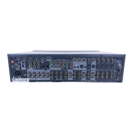
Installation Serial Control Digital audio control connections inputs Digital output REMOTE DIGITAL INPUTS LOCAL TAPE RS232 CONTROL TUNER 50/60Hz TRIGGER ZONE 2 100–240VAC~ MAX 40VA LEFT CENTRE SUB 2 GROUND LIFT (IN) RIGHT SUB 1 SUB 3 OUTPUTS Ground lift Power supply Multichannel connector... -
Page 7: Audio Connections
AV9 off and select the ‘MC’ setting on the switch and test the record deck again. Please note that if the AV9 is set to ‘MM’ and the record deck has a ‘MC’ cartridge fi tted, testing these together will not cause any damage to either the AV9 or the record deck. -
Page 8: Zone 2 Connections
Zone 2 receives only signals obtained by the AV9 from the analogue audio and composite video inputs. The analogue inputs are required because there is no analogue-to-digital, digital-to-analogue or DSP processing available for Zone 2 signals;... -
Page 9: Video Connections
Video connections Important notes As described on page 5, the AV9 performs no video format conversion between component, RGB, S-video or composite. Therefore, wherever possible, connect multiple video outputs from your video sources. This enables use of the higher quality video connection for the main system and the corresponding S-video or composite connection for the record and Zone 2 outputs. -
Page 10: Control Connections
HDMI source. It is important to realise that analogue video sources cannot be routed by the AV9 to the HDMI output, nor can the HDMI inputs be converted to analogue video (of any sort). The AV9 acts simply as a switching device, selecting one of the inputs and routing it to the output. -
Page 11: Configuring The Av9
The AV9 defaults to the NTSC video standard – most display devices can synchronise to this automatically. For PAL-only display devices, press and hold the AV9 will change to the PAL video standard. As soon as a video signal is input to the AV9, it detects automatically which standard it is and switches to it. -
Page 12: Basic Setup
Full Page mode. Video Status: This setting controls the trigger sockets on the rear panel of the AV9 ( useful only if you wish to use SCART connections from the AV9 (SCART refers to the multipole A/V connector usem m... - Page 13 NTSC or PAL. Sync On Green: This applies only if RGB video is used. On makes the AV9 feed the video synchronisation signal out with the green signal. Some RGB-driven display devices require this to lock on to the video signal coming in, while others need the video synchronisation on a separate lead.
- Page 14 3 – Speaker delay settings Note: Only enter these delay settings once you have specifi ed what delay units (i.e., Time, Imperial or Metric) you will be using, or the information will be lost when changing units. The measurement units can be specifi ed on page 1 of this menu (described on page 12).
- Page 15 DVD-A Sub Level: This setting allows compensation for subwoofer level gain from external decoders or sources (such as DVD-A players). When decoding digital inputs, the AV9 follows the convention for products of this type and sets the subwoofer level 10dB higher than that of the other channels. Source products such as DVD-audio players do not follow this pattern, however, setting the subwoofer level to be the same as the other channels.
-
Page 16: Advanced Setup
– only the setup menus and the main menus are displayed. It is recommended you keep the OSD turned panel of the AV9, you will have no idea if any adjustments you have made to the processor are correct or to your liking. - Page 17 < All Off When the AV9 receives a stand-by command in Zone 1, both Zone 1 and Zone 2 will be switched to stand-by. Note: the setting for Zone 1 Stand-by applies only for putting the AV9 into stand-by mode. Re- activating Zone 1 is always a local function.
- Page 18 ADV 5 – Input trims Input trims: Allows the adjustment of the input sensitivity of the analogue inputs (in Volts RMS) so that each one achieves the optimum dynamic range and sounds similar in loudness to the others. Available level settings are: Low 1V, Reference 2V, Medium 4V, High 8V. The reference level of 2V should be appropriate for most inputs.
-
Page 19: Saving Settings, User Presets And Exiting The Setup Menu
Zone 2 video source Once you have specifi ed the settings you wish to save, highlight the Save text and press 4. After the AV9 has fi nished saving, press OK to return to the ‘Setup Menu Index’. 5. Press to select ‘Exit Setup’... -
Page 20: Front Panel Controls
Front panel controls AV8 PREAMP PROCESSOR POWER E-20... -
Page 21: Remote Control
Remote control E-21... -
Page 22: Operating Your Av9
LED glows red. When not being used, the AV9 may be left in standby mode, as power consumption is low. If you are not using your AV9 for several days we recommend you switch the unit completely off at the front panel. -
Page 23: Stereo Direct
0dB THX Ref: The volume range covers –63dB to +19dB in 1dB steps. Headphones To use headphones with the AV9, plug the headphones into the socket on the left hand side of the front panel. When headphones are plugged into the headphones socket the outputs for the zone to which they are assigned is muted. - Page 24 Effects/FX button ( EFFECT effect modes. The effects are only available when the AV9 is in stereo mode. For more information on the effects, see the section ‘DSP Effects Modes’. This button cycles through the available THX modes. The available THX modes change depending on what mode the AV9 is in and what source material is being played.
-
Page 25: Using The Main Menu Screens
If the audio and video are set to different inputs, they will be reset to be the same when the audio input is next changed. However it is possible to set the AV9 so that they remain separated in the ‘Video Settings’... - Page 26 Zone 2 Status: Turns Zone 2 output On or Off. This should be set to Off if no equipment is connected to the Zone 2 outputs on the AV9. Note: You cannot change the Zone 2 audio or video inputs unless Zone 2 is on. It takes about fi ve seconds to initialise Zone 2.
-
Page 27: Using Zone 2
Using Zone 2 Introduction Zone 2 provides the option for the occupants of the master bedroom, children’s room or kitchen to view or listen to a different source at a different volume level from the main zone (zone 1). If a video feed is provided to Zone 2, then the following menu, unique to a Zone 2 IR receiver, can be called up using the MENU Control via Zone 2 menu... -
Page 28: Surround Modes
There is a link between the mix modes for multi-channel bitstream (e.g., 5.1) and two-channel bitstream (2.0 or 2.1) sources. If a 5.1 source is played in Surround mix mode, the AV9 will remember this for all bitstream sources (e.g., DTS-ES Matrix, Dolby Digital 3.0 etc.) and use the maximum number of speakers the signal is encoded for. -
Page 29: Multi-Channel Source Modes
DTS NEO:6: DTS Neo:6 provides up to six full-band channels of decoding from stereo material. The AV9 will derive separate channels corresponding to the standard home theatre speaker layout. < Cinema: A movie mode designed to reproduce a movie theatre environment. Neo:6 technology allows various sound elements within a channel or channels to be steered separately, and in a way which follows the original presentation naturally. -
Page 30: Thx ® Modes
Dolby Digital 5.1 Surround Ex: This is accessed from the source material automatically selects THX Surround Ex selection (when activated). DTS 5.1: Less common than the Dolby Digital format, but generally recognised within the audio industry as being of superior sound quality. DTS 5.1 delivers surround sound with five full range channels plus an LFE channel. -
Page 31: Dsp Effects Modes
DSP Effects Modes The AV9 has a number of effects modes that can be used to enhance a stereo signal and to make use of the surround loudspeakers. DSP effects modes are only available with stereo source signals. You can listen to the influence of any effect mode by playing a CD, then pressing pause, when the decaying reverberation effect can be heard. -
Page 32: Speaker Installation
Speaker Installation The AV9 allows you to connect up to seven channels of amplifi cation and three active subwoofers in the main system. The output channels correspond to speakers installed in the front left, centre, front right, surround left, surround right, surround back left, surround back right and an active subwoofer (see diagram). -
Page 33: Troubleshooting
< the power button is pressed in. If a red LED is present, the AV9 is in standby mode. Press any source button on the front panel or on the remote control. The unit responds erratically or not at all to the remote control: Check that: <... - Page 34 AV9 to include all the speakers in your system. Unable to select Dolby Digital or DTS decoding modes: The AV9 can only apply Dolby Digital and DTS decoding to sources which have been encoded in the same format.
- Page 35 Component Video connection to AV9 only: It is possible to configure the AV9 by using the front panel as the selected line of the menu is displayed on the front panel, however it is easier using the OSD on your display device.
-
Page 36: Technical Specifications
Supplied accessories E&OE NOTE: All specification values are typical unless otherwise stated. Continual improvement policy Arcam has a policy of continual improvement for its products. This means that designs and specifications are subject to change without notice. E-36 2V rms 10kΩ... -
Page 37: Utility Software
The unit can radiate RF (radio frequency) energy. In some cases this can cause interference with FM and AM radio reception. If this is the case, keep the AV9 player and its connecting cables as far from the tuner and its aerials as possible. Connecting the AV9 and the tuner to different mains sockets can also help to reduce interference. -
Page 38: Scart Connections
SCART connections These pinouts describe the signal connections between the AV9 and your display device input. SCART RGB cable with audio back to processor Signal Audio output B (right) from TV Tuner Audio input B (right) Audio output A (left) -
Page 39: Ir Remote Codes
Philips ‘Pronto’ and similar devices, where it is possible to program remote codes directly into the device. The coding system for the AV9 is based on the Philips RC-5 standard. The main system control uses RC-5 system code ‘16’, so for example, to program in a ‘Standby’ command, use the command ‘16-124’. -
Page 40: Guarantee
This equipment should be packed in the original packing and returned to the dealer from whom it was purchased, or failing this, directly to the Arcam distributor in the country of residence. It should be sent ‘carriage prepaid’ by a reputable carrier — NOT by post. No responsibility can be accepted for the unit whilst in transit to the dealer or distributor and customers are therefore advised to insure the unit against loss or damage whilst in transit. -
Page 41: Appendix: Av9 Serial Programming Interfacee-42
This response gives the zone it is reporting on (Z2 in this case), the setting (MUT), and the current value (a 1, showing it as ON). In order to keep the RS232 controller informed of the current state of the AV9, certain changes in configuration/state will result in the AV9 automatically sending messages, just as if they had been queried using the method above. -
Page 42: Command Descriptions
Command descriptions / Descriptions des commandes / Beschreibung der Befehle / Opvraagcommando’s Query commands / Commandes d’interrogation / Abfragebefehle / Vraagcommando’s ?zPWR ?zMUT ?EFF ?THX ?DEC ?DIR ?zVOL ?zAUD ?zVID ?zSIG E-42 zPWRx, z = zone. Query Power State Interroger état M/A Ein/Aus abfragen Spanningsstatus opvraag zMUTx, z = zone. - Page 43 ?zSTS Query Zone Status. Interroger état Zone Zustand der Zone abfragen Zone status opvraag ?PRE Query Current Preset Interroger présélection actuelle Aktuelle Voreinstellung abfragen Gangbare preselectie opvraag ?TRMs Query Trims Interroger trims Trimms abfrage Instelling opvraag ?BSA Query Bass Trim Interroger trim grave Tiefen-Trimm abfragen Lage toneninstelling opvraag...
- Page 44 General operation commands / Commandes de foncionnenment général / Allgemeine Betriebsbefehle / Commando’s algemene werking ?zPWRx ?zMUTx zFANx ?EFFy ?THXy ?DECy ?zSIG E-44 Power on/off Power marche/arrêt Gerät ein/aus Spanningsstatus aan/uit Mute on/off Mute marche/arrêt Stummschaltung ein/aus Geluidsonderdrukking (Mute) aan/uit Force Analogue Forcer analogique Analog erzwingen...
- Page 45 ?zSTS Zone Status. Displays current state of Audio, Video, Volume, Mute, Audio Signal Type, *Decode/Downmix Mode, *Effect Mode, *THX Mode. * Zone 1 only État Zone. Affiche l’état actuel audio, vidéo, volume, mute, type signal audio, *mode décodage/ mixage, *mode effet, *mode THX. * Zone 1 seulement.
- Page 46 RCTi RCVi COMy LIPy DIMy CTWy PANx HEDz E-46 Record To Tape Select Sélectionner ‘Record To Tape’ Bandaufzeichnung auswählen Bandopname selectie Record To VCR Select Sélectionner ‘Record To VCR’ Videoaufzeichnung auswählen VCR opname selectie y = 0 — 2: Compression 0 = Off/Arrêt/Aus/Uit Compression 1 = Medium/Moyenne/Medium/Medium...
- Page 47 Setup commands – Basic / Commandes de base / Befehle des Setup-Menüs (Basic) / Set-up commando’s – basis GENERAL / GÉNÉRALES / ALLGEMEINE EINSTELLUNGEN / GENERAAL VDSy Volume Display Affichage volume Lautstärkeanzeige Volume Display zMXVy Maximum Volume Volume max. Max. Lautstärke Maximaal volume zMXOy Max On Volume...
- Page 48 LEVELS / NIVEAUX / PEGELEINSTELLUNGEN / NIVEAUS LVLsy SUB / CAISSON DE GRAVE / SUBWOOFER /SUB CRFy STMy LFEy DLFy SSTy DALy NSWy THX / THX / THX /THX TEXx U2Sx BGCx ASAy E-48 y = -10 — +10: Speaker Level settings -10 = –10dB Réglages des niveaux enceintes +10 = +10dB...
- Page 49 Setup commands – Advanced / Réglages : Commandes avancées / Befehle des Setup-Menüs (Advanced) / Set-up commando’s – geavanceerd ADV 1 – SPEAKER EQ / ENCEINTES / LAUTSPRECHER EQUALIZER / LUIDSPREKER BASsy Bass Levels Niveaux grave Tiefenpegel Lage tonen niveaus TRBsy Treble Levels Niveau aigu...
- Page 50 ADV 4 – ZONE 2 / ZONE 2 / ZONE 2 / ZONE 2 FVLx zSBYy CZIx ACCix ADV 5 – INPUT TRIMS / ANALOGIQUE / EINGANGS-TRIMMS /ANALOOG ANSiy ADV 6 – INPUT NAME / NOM D’ENTRÉE / EINGANGSNAME /INGANGSNAAM INPin E-50 Zone 2 Fix Volume...
- Page 51 Save Settings / Mémoriser les réglages / Einstellungen Speichern / Save instellingen SAVy Save Preset Mémoriser présélection Voreinstellung speichern Save preselectie PNMyn Preset Name Nom de présélection Name d. Voreinstellung Preselectie naam Engineering Settings / Réglages techniques / Technikeinstellungen / Engineering instellingen zRC5y RC5 System Code Code système RC-5...
- Page 52 Multi-button presses / Touches multiples / Drücken mehrerer Tasten / Meerdere toetsen drukacties Menu Access / Accès aux menus / Menüzugriff / Menutoegang E-52 Setup Menu Lock Verrouiller les menus de réglage Setup-Menü sperren Instelmenu vergrendeling Test VFD and LEDs Tester affichage et LEDs Display und LEDs testen Test VFD and LED’s...
- Page 53 Display LipSync Shortcut Afficher raccourci synchronisation Verknüpfung zu „LipSync‘ anzeigen Lippensynchronisatie kortweg aanduiding Display Subwoofer Shortcut Afficher raccourci caisson Verknüpfung zu „Subwoofer‘ anzeigen Subwoofer kortweg aanduiding Navigation / Navigation / Pfeiltasten / Navigatie Haut Nach oben Omhoog Down Nach unten Omlaag Left Gauche...
- Page 54 Pembroke Avenue, Waterbeach, CAMBRIDGE CB5 9QR, England Issue B SH170...
Need help?
Do you have a question about the AV9 and is the answer not in the manual?
Questions and answers