Table of Contents
Advertisement
Quick Links
Advertisement
Table of Contents

Related Manuals for Microtest 7630


Summary of Contents for Microtest 7630
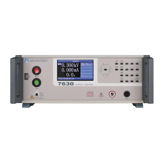
- Page 1 HI-POT TESTER 7630 7605 User Manual Apr 2019...
-
Page 2: Table Of Contents
Table of Contents Precautions before use ......................... 4 Electrification and Electric Shock ..................4 Ground ..........................4 Power ..........................4 Connect the testing cable to the high voltage output terminal ......... 4 Warm up ........................... 4 External control host ......................4 Machine malfunction ....................... - Page 3 Remote Interface Instructions ....................28 Instruction Summary ...................... 28 Instruction Description ....................30...
-
Page 4: Precautions Before Use
1. Precautions before use This tester outputs voltage as high as 5kVac/6kVdc for external testing; accidents will happen if this tester is used incorrectly or improperly. Therefore, in consideration of your own safety, please read the precautions described in this chapter carefully and memorize them in order to prevent accidents from occurring. -
Page 5: General Description
2. General description 2.1 Package and Accessories Standard accessories included with the HT-7630 high voltage tester package should include the following items: 1. HT-7630 high voltage tester *1 2. High voltage testing cable (red) *1 3. Low voltage terminal testing cable (black)*1 4. -
Page 6: Front Panel
2.2 Front Panel (1) Test button (includes PASS indicator): Pressing this button while the machine is in READY status will start performing testing; if the test result passed, this indicator will light up. (2) Abort button (includes FAIL indicator): Pressing this button while the machine is in testing status will stop the test and switch off the high voltage output;... - Page 7 (1) Test button (includes PASS indicator): Pressing this button while the machine is in READY status will start performing testing; if the test result passed, this indicator will light up. (2) Abort button (includes FAIL indicator): Pressing this button while the machine is in testing status will stop the test and switch off the high voltage output;...
-
Page 8: Rear Panel
2.3 Rear Panel (1) High voltage output terminal: Used to connect to expansion box. (2) Low voltage output terminal: Used to connect to expansion box. (3) USB device port: Used to connect to computer; instructions can be used to control the machine from the computer terminal. - Page 9 (3) USB device port: Used to connect to computer; instructions can be used to control the machine from the computer terminal. (4) Expansion box port: This terminal needs to be connected to the expansion box with a cable when connecting an expansion box. (5) AC power socket: AC power input terminal;...
-
Page 10: Basic Operations
3. Basic Operations 3.1 Function Block Diagram Standby System/Sys Function/Func Setup/Setup File/File screen/Ready MODE Save As.. Baud Rate Key Lock System/Sys VOLT FREQ Load File Configuration/ Pass Hold Time Upload Data Config Del. File Setup/Setup Trig Wait Time Key Sound Ramp New File Alarm Mode... -
Page 11: Standby Screen
3.2 Standby Screen (1) Displays the current test mode; the text ACW is displayed when testing AC withstand voltage, the text DCW is displayed when testing DC withstand voltage and the text IR is displayed when testing insulation resistance. (2) Displays the voltage value and current value (the resistance value will be displayed when the measuring mode is IR) of the output terminal, as well as test time for the current measurement;... -
Page 12: System Settings (System)
RS-232. The data storage path is \7630\STAT\current test file name.csv. When the function is set as BOTH, the two actions above will be performed simultaneously. -
Page 13: Function Setting (Func)
3.4 Function Setting (FUNC) (1) Key Lock: The key lock is the function used to prevent people from changing test conditions due to misuse; when the function is enabled, users can only start and stop tests, but cannot change settings data. When this function is enabled, to release the key lock function, the password originally set must be entered in order to release it. -
Page 14: Specification Settings Description 1 (Setup)
3.5 Specification Settings Description 1 (SETUP) (1) STEP: Step number; each file supports a maximum of only 16 steps. To add a second step, the COPY software button needs to be pressed. Steps are also deleted by pressing the DEL software button;... -
Page 15: Specific Setting Description 2 (Setup)
3.6 Specific Setting Description 2 (SETUP) (1) OPEN: Open circuit detection sensitivity. When performing withstand voltage test, if the high voltage test cables were not connected to the DUT correctly, the measurement current will become lower and causing the result to be determined as a PASS. When this function is enabled (settings value not 0), the machine will first use low voltage to measure the capacitance on the DUT when performing high voltage tests (measuring time approximately 200ms);... - Page 16 (3) High voltage output time and result determination timing: The two figures below mainly explain that when the user presses the TEST button, the timing to determine the result, especially during the delay time and rising time of IR, and the determining of maximum and minimum limits are not performed, and only the maximum limit is determined during the rising time of ACW and DCW mode.
-
Page 17: File Management (File)
3.7 File Management (FILE) (1) Save As..: Save as new file; saves the file set using a new file name (a maximum of 30 sets can be saved inside this machine). After entering the save screen, the screen will display all files already saved inside;... - Page 18 (2) Load File: Read file; reads the file that was saved. After entering the read file screen, the screen will display all files saved inside; if a portable access device is inserted in the USB slot, the USB icon will appear at the top-right corner of the screen. At this time, the software buttons can be pressed to choose whether to read the file on the USB memory or internal memory.
- Page 19 (6) Copy File From USB: Copies the settings file on the USB drive to inside the machine; if the file names are the same, it will be overwritten directly. After entering the menu, the screen will display the file names currently saved on the USB drive. Press the software buttons to select the three functions OPT, ALL or COPY;...
-
Page 20: Start Test
4. Start test 4.1 Before testing (1) Confirm whether the specification settings are correct. (2) Confirm whether the machine and DUT is connected properly. (3) Check whether the text READY is displayed on the message field. (4) Press the TEST button to perform testing... -
Page 21: Testing
4.2 Testing (1) The message field displays the text TEST. (2) The high voltage output indicator on the front panel lights up. (3) Output voltage measurement and leakage current measurement. (4) Test time count; if the test time exceeds 100 seconds, only the whole number part will be displayed. -
Page 22: End Test
4.3 End Test (1) Interrupt testing by pressing the ABORT button (2) Measured current/resistance exceeded the maximum value set (HI-LIMIT) (3) Measured current/resistance is less than the minimum value set (LO-LIMIT) (4) Leakage current exceeded the maximum measurement value (Break Down) (5) Arc exceeded the setting value (Arcing) (6) Output safety switch enabled (Inter Lock) (7) DUT terminal open circuit (OPEN) -
Page 23: Releasing Determined Result
4.4 Releasing Determined Result (1) After the testing time has passed, the PASS (green) indicator will light up and the text PASS will appear on the screen. When the PASS HOLD time is reached, the screen will return to the READY status and the PASS indicator will go off. -
Page 24: Remote Control I/O Description (Remote)
5. Remote Control I/O Description (REMOTE) On the rear panel of the tester there is a socket for remote control (REMOTE); insert the control cable into this slot when you want to use external signal to control the output of this machine. Since it is controlled by external signals, prevent testing personnel from touching the high voltage output terminal and causing danger. - Page 25 Instructions: PIN1-PIN8 are open collector outputs and they do not output of any voltages or signals; the current that flows through the contacts must not exceed 50mA (1) TRIG (Pin10): When short-circuited with Pin15 (COM), it functions the same as the function of the TEST button on the front panel.
-
Page 26: Rs-232/Usb Device Instructions
6. RS-232/USB DEVICE Instructions 6.1 RS-232 interface specifications Baud Rate: 9600/19200/38400/57600/115200; can be set in System mode Transmission bit: 1 start bit, 8 data bits and 1 end bit. 6.2 Command Format The function of this machine’s RS-232 interface is to input instruction strings composed of ASCII codes to achieve remote control and settings functions. -
Page 27: Cables And Connecting Methods
6.4 Cables and Connecting Methods Cables D DUB female terminal D DUB female 6.5 USB DEVICE Interface Specifications Interface I/O USB Specification 2.0 Self-powered Transfer rate: MAX 12Mbps (Full Speed) Instruction string end code LF or EOM while receiving LF + EOM while transmitting Vendor ID 0x1FC9 Product ID... - Page 28 7. Remote Interface Instructions 7.1 Instruction Summary Shared Instructions *CLS *IDN? *OPC *OPC? *OPT? *RCL *SAV SCPI instructions :CONFigure :KLOCk <ON , OFF, 1, 0> :ALARm <ALL,PASS, FAIL,OFF> :PHOLd <50ms,100ms,500ms,1s,2s,5s,INFinity> :TGWAit <NRf> :TMODe <SINGLE,MULTI> :TMODe :MULTi :TSOUrce <AUTO,TRIG> :TMODe :MULTi :BREAk <FAIL,OFF>...
- Page 29 :FILE? :RESU? :STAR :STOP :SYSTem :AUREply <ON , OFF, 1, 0> :KYSOund <ON , OFF, 1, 0> :ALARm [:VOLUme] :PASS <numeric> :ALARm [:VOLUme] :FAIL <numeric> :ERROr? :TEST :ABORt :EXECute...
- Page 30 7.2 Instruction Description Shared Instructions Instruction Function *CLS Clears the values of all registers. *IDN? Reads the basic information of the device; the output format is separated by commas, which are: manufacturer, machine model number, machine serial number and firmware version, respectively. *OPC Operation completed command.
- Page 31 next step and test> :CONFigure:TMODe:MULTi:BREAk <FAIL,OFF> This command sets the interrupt test source during multi-step test. Example: CONF:TMOD:MULT:BREA FAIL Example description: Set that if one of the steps was determined as FAIL during multi-step test mode, stop the test immediately. Example: CONF:TMOD:MULT:BREA? Return data: FAIL <stop test when determined as FAIL>...
- Page 32 Example: EDIT: DWEL? Return data: +1.00000E+00 <1s> :EDIT: CHANnel : POSItive < numeric > <7630 model invalid> This command sets the high voltage terminal output channel. Example: EDIT:CHAN:POSI 1,2,3,4 Example description: Sets the high voltage output as channels 1, 2, 3 and 4.
- Page 33 Example: EDIT:STEP:ADD 2 Example description: Add the test step STEP2. :EDIT: STEP:CONDition? < numeric > This command queries the test step conditions. Example: EDIT:STEP: COND? 2 Example description: Queries the test conditions of step 2. Return data: ACW,1.00kV,50HZ,26.00mA, 0.00mA, 0.1s, 1.0s,0, 0.00mA,OFF. Order of the contents: Test item, voltage, frequency, maximum limit, minimum limit, rise time, test time, arc sensitivity, offset deduction value and determination delay time.
- Page 34 This command starts the test; it functions the same as the TEST button on the panel Example: STAR. :STOP This command stops the test; it functions the same as the ABORT button on the panel Example: STOP. : SYSTem: AUREply <ON , OFF, 1, 0> This command sets the automatic reply function of RS-232.
- Page 35 Appendix 1 Error message -100 Command error Instruction error -102 Syntax error Syntax error -103 Invalid separator Invalid separation character discovered in the instruction string -108 Parameter not allowed Received parameters that are not allowed -109 Missing parameter Parameter missing -112 Program mnemonic too long Simple program header exceeded 12 characters...
Need help?
Do you have a question about the 7630 and is the answer not in the manual?
Questions and answers