Table of Contents
Advertisement
Quick Links
Advertisement
Table of Contents

Related Manuals for Microtest 6910


Summary of Contents for Microtest 6910
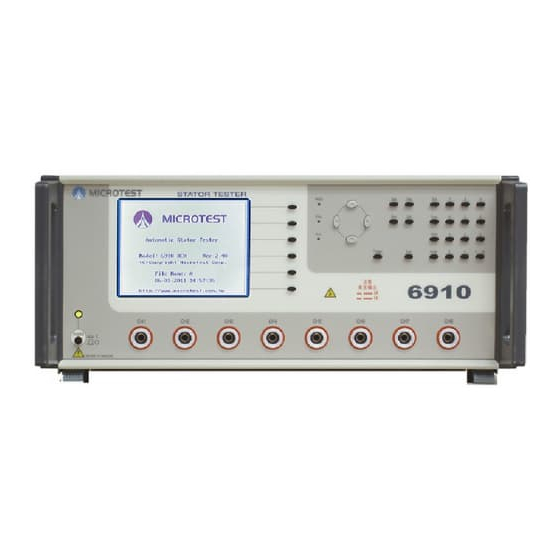
- Page 1 User Manual Motor Stator Tester 6910 S/W Ver Firmware Date Oct 2009...
-
Page 2: Table Of Contents
MICROTEST CATALOG 1. BEFORE USE ........................1 1.1 Product Introduction......................1 1.2 Product Characteristic ...................... 1 SPEC INSTRUCTION ......................2 SAFETY INSTRUCTION ....................4 INSTALLATION ........................ 6 4.1 Front Panel Function ......................6 4.2 Back Panel Function ......................7 OPERATION INSTRUCTION..................8 5.1 Before Use ........................ - Page 3 MICROTEST 5.5.5 Circuit Resistance Setting..................30 5.5.6 Resistance Balance Setting ..................33 5.5.7 Test Sequence Setting ..................... 33 5.6 Start Testing ........................34 5.6.1 Test Progress Procedure ..................34 5.6.2 Testing Message Analysis ..................36 REMOTE INSTRUCTION ....................38 6.1 Introduction ........................38 6.2 Interior Remote Instruction .....................38 6.2.1...
-
Page 4: Before Use
MICROTEST 1. BEFORE USE 1.1 Product Introduction MT-6910S is a tester which exclusive made for Motor Stator tester and it includes 8 4-wire testing independent testing points. The testing items are including DC Resistor testing and Impulse / Surge Testing which can well examined your product and also speed up the testing. -
Page 5: Spec Instruction
MICROTEST 2 SPEC INSTRUCTION DC Resistor ◆ Measuring Range 1mΩ~100KΩ ◆ Stable Accuracy Low Resistance: 1mΩ~100mΩ ± (0.1%±2mΩ) High Resistance: 1Ω~100kΩ ± 0.1% 1kΩ~10kΩ ± 2% 10kΩ~100kΩ ± 5% Hipot ◆ Measuring Voltage AC 0.1kV~5kV ±5% DC 0.1kV~6kV ±5% ◆... - Page 6 MICROTEST Layer Short ◆ Measuring Voltage 0.1kV~5kV ±1% ◆ Measuring Item Waveform area, waveform area difference, waveform tremor, waveform comparison, flutter value ◆ Stable Accuracy Other Spec ◆ Measuring Pin 8 Channels ◆ Display / Sound Device Pass / Fail graphic display / Sound device ◆...
-
Page 7: Safety Instruction
110V 98~123V 6905 5A, 250V 220V 192~264V 6910 Full Range 100~264V 5A, 250V 5. Connect testing cable with HV output port Please make sure the power is off when HV cable plug in the ports of the tester, and ensure that the exterior of cables are not broken or come off... - Page 8 7. Exterior Control Do not touch HV port and DUT during operation 8. Breakdown Stop the operation and contact your agent or Microtest immediately while there’s abnormal condition with the testers 9. End Up Turn off the power when the tester is not in use and do not turn the power on and off continuously 10.
-
Page 9: Installation
MICROTEST 4 INSTALLATION 4.1 Front Panel Function (2) (3) (6) (7) (10) (11) (12) (1) LCD Monitor (2) S1~S6 Operation Soft Key (3) PASS / FAIL & HV instruction light (4) Cursor Control Key (5) Function Key (6) System Key... -
Page 10: Back Panel Function
MICROTEST 4.2 Back Panel Function (9) (10) (11) (12) (1) RS-232 Output Port (For 6905) (2) RS-232 Input Port (For PC) (3) Printer Port (4) Remote Port 1 (5) Remote Port 2 (For double fixture) (6) 6905 HV Input Port (Postitive) -
Page 11: Operation Instruction
Press S1 under Function Menu and enter Self Test mode and start the self testing. Test items are CPU, RAM, ROM, EEPROM, CLOCK…etc. If test result is NG, power off the tester and contact your agent or Microtest Corp. to repair the instrument... -
Page 12: Temperature Testing Configuration
MICROTEST Figure 5.2.1-2 5.2.3 Temperature Testing Configuration PessS4 under Function Menu and enter Temperature Testing Configuration mode. The function helps the testing progress under usual temperature and which make the test results more accuracy 圖 5.2.3.1 Configuration: Press S2 and manager code under Temperature Testing Configuration mode and start the calibration. -
Page 13: System Version Information
MICROTEST Figure 5.2.3-2 Fahrenheit / Centigrade: Press under Temperature Test Configuration mode to switch the temperature module. Figure 5.2.3.3 5.2.4 System Version Information Press S6 at the Function Mode to enter System Info, the function can provide you the information of the Model Number, Firmware Version, Release Date,... -
Page 14: System Instruction
MICROTEST Figure 5.2.4.1 5.3 System Instruction 5.3.1 System Entering Setting Press at the main menu to enter System Setup Menu Figure 5.3.1.1 5.3.2 System Environment Setting Press S1 to enter System Setup. If want to modify the contents, use navigation... -
Page 15: Test Configuration Setting
Standard, Extend, Unused Power On Self-Test: Press to Lock or Unlock the Power On Self-Test WARNING: If self testing is NG, please turn off power immediately and contact your agent or Microtest Corp. immediately Language: Press to change language 5.3.3... - Page 16 MICROTEST Figure 5.3.3.1 Temp. Correction: Press to turn on / off the function Warning: Please turn off Temperature Correction function during configuration. Press S1 to select setup item as follow… Test Alarm: None è No alarm whether the result is pass or fail All è...
-
Page 17: System Time Setting
MICROTEST Figure 5.3.3.2 Break On Failed Step: Press S1 to turn on / off the function. Stop testing when result is failed Auto Print Test Data: Press S1 to turn on / off the function. Print out the information when the sample is fail... -
Page 18: Password Setting
Password Setting Press under System Setting and enter the password into a text box. After enter the original code (6910), re-enter the new password (maximum 8 digits number) and re-enter the new numbers again to confirm the new password Figure 5.3.5.1... -
Page 19: File Management
MICROTEST Figure 5.3.5.3 File Management 5.4.1 File Management Setting Press FILE under Main Menu to enter File Management Figure 5.4.1.1 5.4.2 Load File Press S1 under File Management Menu to enter Load File. If file is using, the figure will shows “@” in front of file name. Use navigation key to move the... -
Page 20: Create New File
MICROTEST Figure 5.4.2.1 5.4.3 Create New File Press S3 under File Management to enter Create New File. Use navigation key to move the cursor and press S3 to select the alphabet, press S4 to delete and key in the file name press S1 to save the file name. -
Page 21: Delete File
MICROTEST Figure 5.4.4.1 5.4.5 Delete File Press S5 under File Management and enter Delete File. Use navigation key to move the cursor you want to delete and press S1 to delete. Figure 5.4.5.1 5.5 Setting Instruction 5.5.1 Test Setting Menu... -
Page 22: Insulation Test Setting
MICROTEST Figure 5.5.1.1 Caution: Please be noted that the testing items for 6910 includes: Insulation, Hipot, Surge, Resistance, O/S and more. Insulation and Hipot are only for the testing which connect with 6905, if the instrument does not connect with 6905, please turn off these 2 items. - Page 23 MICROTEST Figure 5.5.2.2 Voltage: Move the cursor to Voltage and use numeric key to set up voltage value, the maximum voltage is 1.0kV, the minimum voltage is 0.1kV Dwell: High voltage output sequential times. Use numeric key to set up, maximum value is 99.9 second, minimum value is 0.1 second...
-
Page 24: Hipot Test Setting
MICROTEST 5.5.3 Hipot Test Setting Press under Testing Function Setting to enter Hipot Test Setting. Figure 5.5.3.1... - Page 25 MICROTEST Channel +/-: Press under Insulation Test Setting to enter High voltage Channel Setting text box. Use navigation key to move the cursor to the channel and press to start the setting. After the setting, press confirm. Figure 5.5.3.2 Voltage / Frequency: Move the cursor to Voltage and use numeric key to set up voltage value, the maximum value is AC 5.0kV, DC 6.0kV, the...
-
Page 26: Impulse (Surge) Test Setting
MICROTEST be 1. This function is to make users speed up testing. 5.5.4 Impulse (Surge) Test Setting Press under Testing Setting mode to enter Impulse / Surge Setting Figure 5.5.4.1 Channel +/-: Press under Insulation Test Setting to enter High voltage Channel Setting text box. - Page 27 MICROTEST of DUT. Move cursor to Learning and press to enter setting screen, after entering, connect standard sample with Hipot output terminal and press to learn. If the waveform is too wide or too narrow, press to widen or to narrow, or move the cursor to width and key the value directly. Under this mode, it can also adjust voltage and testing mode after learning, press to exit.
- Page 28 MICROTEST Figure 5.4.4.4 Area Size: This item is to check the difference between testing waveform and standard waveform. Move the cursor to Area Size and use numeric to set up tolerance rate and then press to enter Testing Mode (please note that the...
- Page 29 MICROTEST Figure 5.4.4.6 Differential Area Size: Move cursor to differential area size and press S1(testing option), and use numeric key to enter tolerance rate. Press to enter Testing Mode and use S2~S5 to set up testing range. After the setting, press S1 to start the pre-test.
- Page 30 MICROTEST 圖 5.4.4.8 Flutter Value: Move cursor to Flutter value and press (Test Selecting) key, use numeric key to enter standard values, if the test result is larger than the value, the result is fail. Press to enter Testing Mode and use S2~S5 to set up testing range, after the setting, press to start pre-test.
- Page 31 MICROTEST Figure 5.4.4.10 Waveform Comparison: Move the cursor to Waveform Comparison and press (testing option), and use numeric key to enter tolerance rate. Press to enter Testing Mode and use S2~S5 to set up testing range, after the setting, press to start pre-test.
- Page 32 MICROTEST Figure 5.4.4.12 Corona Value: Move the cursor to Corona Value and press (Testing Option), using numeric key to enter the standard value. Press to enter Pre-Testing Mode and then press to start the pre-test, in the meantime there’ll be a corona value displayed at the right...
-
Page 33: Circuit Resistance Setting
MICROTEST Figure 5.4.4.14 5.5.5 Circuit Resistance Setting Press under Testing Item Setup mode to enter Circuit Resistance Setting Channel+/- : Use numeric key to set up the value for the channel under RDC Test Setting Mode. After entering [CH+], the instrument will automatically set up the next channel. - Page 34 MICROTEST Figure 5.5.5.2 Max / Min Value: Move the cursor to Max or Min and key in the value of the standard range, or press conversion key to key in percentage rate directly, the instrument will convert the value and fill in Max / Min blank automatically.
- Page 35 MICROTEST Delay: Use navigation key to move cursor to Delay, and use numeric key o setup delay time Zero: Use numeric keys to enter value or press to offset automatically. If press S2, there’ll be an remind text box to ask user to short the channels to fill in the which want to offset.
-
Page 36: Resistance Balance Setting
MICROTEST 5.5.6 Resistance Balance Setting Test the difference value of 2 sets of coils. Press under Testing Item Setup to enter Resistance Balance Test Setting 圖 5.5.6.1 RefA / Ref B: RefA & RefB must be 2 groups of coils which are going to compare. -
Page 37: Start Testing
MICROTEST Figure 5.5.7.1 On / Off: Used navigation key to move the cursor and selected open or close testing items by pressing soft key Forward / Backward: Use navigation key to move the cursor to test item and press to backward, after the setting press... - Page 38 MICROTEST Figure 5.6.1.2 When press TRIG, Hipot will be outputted and the indicator light will be lightened. After testing, the test results will be shown on the screen also the Test Completed description If Impulse / Surge short is opened, press S6 after the testing in order to check the waveform and related values.
-
Page 39: Testing Message Analysis
MICROTEST Figure 5.6.1.4 If the test result is failed, it will be marked to let the operator easy to identify 圖 5.6.1.5 5.6.2 Testing Message Analysis Hipot Test Result Description Current is over the standard value Current is below the standard value... - Page 40 MICROTEST Insulation Test Result Description Current is over the standard value Current is below the standard value BREAK DOWN DUT Hi-Pot is fail ARCING DUT have corona value LINK ERR De-connected with 6905 Resistance Coils and Balance Test Result Description...
-
Page 41: Remote Instruction
6. REMOTE INSTRUCTION 6.1 Introduction MT-6910 inhabit with remote control, it can be controlled by exterior signal and output test result. To get test result more thoroughly and use test items as signal or classifying the fail DUT automatically, please purchase the remote box additionally. -
Page 42: Circuit Illustration
MICROTEST signal is LOW STOP Exterior start the instrument signal, the action of signal is LOW — Interior DC5V Output +12V Interior DC12V Output — 6.2.3 Circuit Illustration Signal Illustration... - Page 43 MICROTEST PLC Control Range...
-
Page 44: Exterior Remote Instruction
MICROTEST 6.3 Exterior Remote Instruction 6.3.1 Remote Drive Ability Power Output Spec: DC5V, 40mA Signal Out put Spec: Exterior power DC3V~36V, 100mA SIGNAL OUT/IN DESCRIPTION PASS If all DUT test results are pass, out put is LOW DUT_1DCR FAIL DUT 1 DCR test result is fail, output is LOW... - Page 45 MICROTEST FINISHED Finished all DUT testing, output is LOW Test pin connect DUT automatically. Testing output is Low. Please setup Delay function and electromagnetic Electromagnetic must be connected with exterior DC power and the exterior power negative terminal must be connected with...
-
Page 46: Circuit Illustration
MICROTEST 6.3.3 Circuit Illustration Signal Illustration... - Page 47 MICROTEST PLC Control...
- Page 48 MICROTEST TIME LIMIT DESCRIPTION >10mS The limit time of start exterior signal must over 10mS >200mS Delay time. If not using this function the value should be 0 Start testing of output signal Testing time...
-
Page 49: Calibration Procedure
MICROTEST 7 CALIBRATION PROCEDURE DC calibration available, please ensure to warm up the instrument at least 30 minutes in order to make the testing value correct. 7.1 Enter Configuration Procedure Press FUNC key under main menu and then press S2 to enter H/V CAL. The password... -
Page 50: High Voltage Output Calibration
MICROTEST 7.2 High Voltage Output Calibration Use S1 and S2 to adjust the voltage, and please adjust the value of CODE and READING the same if possible. After the adjustment, press ENTER to move next time Figure 7.2.1 UP: Press... -
Page 51: High Voltage Value Setting
MICROTEST Figure 7.3.1.1 7.3.2 High Voltage Value Setting Use numeric key to setup high voltage value. High voltage range is 0.2kV~5KV. If the setting value smaller than 0.2kV and larger than 5KV, the instrument will insert 0.2kV and larger than 5KV, the instrument will insert 0.2kV and 5KV... - Page 52 MICROTEST 總公司(Headquarters) Tel:886-2-26983877 Fax:886-2-26984089 Email:marketing@microtest.com.tw sales@microtest.com.tw 蘇州(Suzhou) Tel:86-512-66578260 Fax:86-512-66578260 東莞(Dongguan) Tel:86-769-88482136 Fax:86-769-88482135...
Need help?
Do you have a question about the 6910 and is the answer not in the manual?
Questions and answers