Table of Contents
Advertisement
Quick Links
Advertisement
Table of Contents

Related Manuals for Microtest CT-8700


Summary of Contents for Microtest CT-8700
- Page 1 Universal Cable/Harness Tester 8700 User Manual...
- Page 2 We trust Microtest can be your best partner. We trust Microtest can be your best partner. We trust Microtest can be your best partner.
-
Page 3: Table Of Contents
Contents Contents Contents Contents CHAPTER I CHAPTER I GENERAL EXPOSITION GENERAL EXPOSITION..........................................1 1 1 1 CHAPTER I CHAPTER I GENERAL EXPOSITION GENERAL EXPOSITION ........................................ PACKAGE & EQUIPMENT......................... 1 SYMBOL & WORD..........................1 GENERAL OPERATION GUIDELINES ..................... - Page 4 CT CT CT CT- - - - 8700 8700 8700 User 8700 User User’s Guide User s Guide s Guide s Guide II.1.C.B RLC ..............................14 II.1.C.C INSULATION ............................. 15 II.1.C.D WITHSTANDING..........................16 II.1.D CALIBRATION ..........................17 II.1.D.A OPEN/SHORT CALIBRATION ......................18 II.1.D.B CONDUCTANCE CALIBRATION....................
- Page 5 Contents Contents Contents Contents II.2.B.C PRINTER DATA REPORT......................... 30 II.2.C DATE & TIME SETUP........................30 II.2.D PASSWORD SETUP........................31 II.2.E SET OUTPUT PORT .......................... 32 II.3 PRINT FUNCTION..........................33 II.4 OPEN/SHORT SETUP & TEST ......................34 II.4.A O/S THRESHOLD SETUP........................34 II.4.B O/S SCANNING SPEED........................
- Page 6 CT CT CT CT- - - - 8700 8700 8700 User 8700 User User’s Guide User s Guide s Guide s Guide III.3.B OPEN NEW FILE ..........................46 III.3.C DELETE FILE ............................. 46 III.3.D SORT FILE............................47 III.4 VIEW MODE ............................48 APPENDIX A APPENDIX A APPENDIX A...
-
Page 7: General Exposition
Chapter I Chapter I Chapter I General Exposition I.1 I.1 Package & Equipment Standard equipment included in the CT-8700 professional Cable/Harness Tester are listed below: CT-8700 Pro. Cable/Harness Tester Power cord & Power line adapter User’s Guide I.2 I.2 Symbol & Word [xxxx] Fast Key (i.e. -
Page 8: General Operation Guidelines
CT CT CT CT- - - - 8700 8700 8700 User 8700 User User’s Guide User s Guide s Guide s Guide I.3 I.3 General Operation Guidelines Alphanumeric Input When save a file that need key in alphanumeric, this series is use the Edit Key. The first time pressing is number, the second to fourth pressing each meaning follow the number key from left to right side of the top capital, For example as below: Key Pressed LCD Display... -
Page 9: Tester Tour
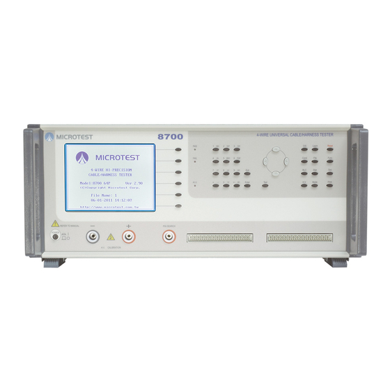
CHAPTER CHAPTER Ⅱ Ⅱ Ⅱ Ⅱ System Function & Configuration CHAPTER CHAPTER System Function & Configuration System Function & Configuration System Function & Configuration I.4 I.4 Tester Tour I.4.A I.4.A I.4.A I.4.A The Front Panel (1) LCD Display (2) S1~S6 SoftKeys (3) PASS &... -
Page 10: I.4.Btest Points
CT CT CT CT- - - - 8700 8700 8700 User 8700 User User’s Guide User s Guide s Guide s Guide I.4.B I.4.B I.4.B I.4.B The points (1) This series is 4 Wire measurement, it can test micro-resistance, but each test point must have 2 connected point with instrument. - Page 11 CHAPTER CHAPTER Ⅱ Ⅱ Ⅱ Ⅱ System Function & Configuration CHAPTER CHAPTER System Function & Configuration System Function & Configuration System Function & Configuration (4) When change over from 4 wire to 2 wire measure mode, simply short 2 pins together then connect to DUT.
-
Page 12: I.4.Cthe Rear Panel
CT CT CT CT- - - - 8700 8700 8700 User 8700 User User’s Guide User s Guide s Guide s Guide I.4.C I.4.C I.4.C I.4.C The Rear Panel (12) RS-232 Port(Reserved) (13) RS-485 Port(Reserved) (14) Remote Port (15) Printer Port (16) GPIB Port(Reserved) Please be sure AC voltage setting is consistent with applied voltage. -
Page 13: System Installation
CHAPTER CHAPTER Ⅱ Ⅱ Ⅱ Ⅱ System Function & Configuration CHAPTER CHAPTER System Function & Configuration System Function & Configuration System Function & Configuration I.5 I.5 System Installation Operation Procedure (a) Be sour the AC input voltage selecter on the rear panel, power supply is set to the proper position (AC 115 or 230V) (b) Connect the converter and DUT cable (c) Turn on the power the system will process self -test... -
Page 14: Key Definition
CT CT CT CT- - - - 8700 8700 8700 User 8700 User User’s Guide User s Guide s Guide s Guide I.6 I.6 Key Definition I.6.A I.6.A I.6.A I.6.A Syskey Group [Func] Function Menu [Sys] System Configuration Menu [Print] Printing Menu I.6.B I.6.B... -
Page 15: C C C C Hapter
CHAPTER CHAPTER Ⅱ Ⅱ Ⅱ Ⅱ System Function & Configuration CHAPTER CHAPTER System Function & Configuration System Function & Configuration System Function & Configuration Chapter II Chapter II Chapter II Chapter II System Function and Configuration System Function and Configuration, including Main Function .System Configuration Setup and Printing Function, is described detail as following. -
Page 16: Ii.1.Aselftest
CT CT CT CT- - - - 8700 8700 8700 User 8700 User User’s Guide User s Guide s Guide s Guide II.1.A II.1.A II.1.A II.1.A Selftest The SELFTEST routine is to test the CPU, RAM, ROM, EEPROM, and CLOCK. Operation Procedure (a) Press [Func] (b) Press [↑] or [↓] to select the item and press[Enter]... -
Page 17: Ii.1.Bsystem Version Information
CHAPTER CHAPTER Ⅱ Ⅱ Ⅱ Ⅱ System Function & Configuration CHAPTER CHAPTER System Function & Configuration System Function & Configuration System Function & Configuration II.1.B II.1.B II.1.B II.1.B System Version information This function provides the instrument information including Model/Test Capability/Software Version/Edition/Released Date/ Total File Space and Free File Space Operation Procedure (a) Press [Func], useing [↑] or [↓] to select the item (b) Press [Enter],LCD diplay as following... -
Page 18: Ii.1.Cmeter Mode
CT CT CT CT- - - - 8700 8700 8700 User 8700 User User’s Guide User s Guide s Guide s Guide II.1.C II.1.C II.1.C II.1.C Meter Mode This function including Conductance/RLC/Insulation/withstanding Operation Procedure (a) Press [Func] (b) Using [↑] or [↓] to select the item (c) LCD display as following (d) Press [Enter] to get in to subordinate display of the Meter Mode (e) LCD display as following... -
Page 19: Ii.1.C.a Conductance
CHAPTER CHAPTER Ⅱ Ⅱ Ⅱ Ⅱ System Function & Configuration CHAPTER CHAPTER System Function & Configuration System Function & Configuration System Function & Configuration II.1.C.a II.1.C.a II.1.C.a II.1.C.a Conductance Operation Procedure (a) Press [Func] using [↑] or [↓] to select the item (b) Press [Enter], LCD display as following (c) Press [↑] or [↓] to select (1) Conductance and press [Enter], LCD display as following... -
Page 20: Ii.1.C.b Rlc
CT CT CT CT- - - - 8700 8700 8700 User 8700 User User’s Guide User s Guide s Guide s Guide II.1.C.b II.1.C.b II.1.C.b II.1.C.b Operation Procedure (a) The operation is the same with conductance, in the subordinate menu of Meter Mode, using [↑] or [↓] to select (2) RLC item, LCD display as following. -
Page 21: Ii.1.C.c Insulation
CHAPTER CHAPTER Ⅱ Ⅱ Ⅱ Ⅱ System Function & Configuration CHAPTER CHAPTER System Function & Configuration System Function & Configuration System Function & Configuration II.1.C.c II.1.C.c II.1.C.c II.1.C.c Insulation Operation Procedure (a) The operation is the same with conductance, in the subordinate menu of meter mode using [↑] or [↓] to select (3) Insulation, LCD display as following (b) Press [Enter] LCD display as following... -
Page 22: Ii.1.C.d Withstanding
CT CT CT CT- - - - 8700 8700 8700 User 8700 User User’s Guide User s Guide s Guide s Guide II.1.C.d II.1.C.d II.1.C.d II.1.C.d Withstanding Operation Procedure (a) The operation is the same conductance, in the subordinate menu of meter mode using [↑] or [↓] to select (4) Withstanding, LCD display as following: (b) Press the [Enter] LCD display as following... -
Page 23: Ii.1.Dcalibration
CHAPTER CHAPTER Ⅱ Ⅱ Ⅱ Ⅱ System Function & Configuration CHAPTER CHAPTER System Function & Configuration System Function & Configuration System Function & Configuration II.1.D II.1.D II.1.D II.1.D Calibration Operation Procedure (a) Press [Func] (b) Use [↑] or [↓] to select the item (c) Press [Enter] to enter to the subordinate mune of calibration mode (d) LCD display as following (e) Change this function will influence the accuracy of the instrument,... -
Page 24: Ii.1.D.a Open/Short Calibration
CT CT CT CT- - - - 8700 8700 8700 User 8700 User User’s Guide User s Guide s Guide s Guide II.1.D.a II.1.D.a II.1.D.a II.1.D.a Open/Short Calibration Operation Procedure (a) Press [Func] and useing [↑] or [↓] to select Calibration (b) Press [Enter] to enter to the subordinate mune of calibration mode (c) LCD display as following (d) Use [↑] or [↓] to select to (1) O/S Cal. -
Page 25: Ii.1.D.b Conductance Calibration
CHAPTER CHAPTER Ⅱ Ⅱ Ⅱ Ⅱ System Function & Configuration CHAPTER CHAPTER System Function & Configuration System Function & Configuration System Function & Configuration (f) Prsee S1[UP] or S2[DOWN] to adjust code (g) After Setup finished, press S5 [DONE] to save or S6 [QUIT] to exit without saving the setup II.1.D.b II.1.D.b... -
Page 26: Ii.1.D.c Dc H//V Calibration
CT CT CT CT- - - - 8700 8700 8700 User 8700 User User’s Guide User s Guide s Guide s Guide II.1.D.c II.1.D.c II.1.D.c II.1.D.c DC H//V Calibration Operation Procedure (a) Operation is the same before, in the subordinate mune of calibration mode, using [↑] or [↓] to select (3) DC H/V Cal , LCD display as following (b) Press [Enter], LCD display as following (c) Press S1[UP] or S2 [DOWN] to adjust code, let the reading value match or... -
Page 27: Ii.1.D.d Ac H/V Calibration
CHAPTER CHAPTER Ⅱ Ⅱ Ⅱ Ⅱ System Function & Configuration CHAPTER CHAPTER System Function & Configuration System Function & Configuration System Function & Configuration II.1.D.d II.1.D.d II.1.D.d II.1.D.d AC H/V Calibration Operation Procedure (a) Operation is the same before, in the subordinate menu of calibration, use [↑] or [↓] to select (4) AC H/V Cal. -
Page 28: Ii.1.D.e Insulation Calibration
CT CT CT CT- - - - 8700 8700 8700 User 8700 User User’s Guide User s Guide s Guide s Guide II.1.D.e II.1.D.e II.1.D.e II.1.D.e Insulation Calibration Operation Procedure (a) Operation is the same before, in the subordinate menu of calibration, using [↑] or [↓] to select (5) Insu.Cal. -
Page 29: Ii.1.Epin Search
CHAPTER CHAPTER Ⅱ Ⅱ Ⅱ Ⅱ System Function & Configuration CHAPTER CHAPTER System Function & Configuration System Function & Configuration System Function & Configuration II.1.E II.1.E II.1.E II.1.E Pin Search The function can automatic show the pin address contacted that we select Operation Procedure (a) Press [Func] (b) Using [↑] or [↓] to select this item... -
Page 30: Ii.1.F 4 Wiring Circuit Test
CT CT CT CT- - - - 8700 8700 8700 User 8700 User User’s Guide User s Guide s Guide s Guide II.1.F II.1.F II.1.F II.1.F Fixture Wiring Circuit test This function is to check whether the fixture has made a 4 wire connection. If it shows OK that can be 4 wiring circuit, if NO that means wrong cable connect or without contact. -
Page 31: Ii.2 System Setup
CHAPTER CHAPTER Ⅱ Ⅱ Ⅱ Ⅱ System Function & Configuration CHAPTER CHAPTER System Function & Configuration System Function & Configuration System Function & Configuration II.2 II.2 II.2 II.2 System setup System Setup includes system configuration and test condition setup. The details describe as following. -
Page 32: Ii.2.A.a Power On Self-Test
CT CT CT CT- - - - 8700 8700 8700 User 8700 User User’s Guide User s Guide s Guide s Guide (d) LCD display as following (e) Use [↑] or [↓] to select a setup item (f) If need, press S1[PROG] to change, after setup finished, press [Enter] (g) Complete setup, press [Exit] to leave II.2.A.a II.2.A.a... -
Page 33: Ii.2.A.d Key Operation
CHAPTER CHAPTER Ⅱ Ⅱ Ⅱ Ⅱ System Function & Configuration CHAPTER CHAPTER System Function & Configuration System Function & Configuration System Function & Configuration II.2.A.d II.2.A.d II.2.A.d II.2.A.d Key Operation This instrument provide key protection that to avoid any data be modified, the default setup is |Unlock | If want to select key protective or remove it which have to enter passwords, the detail please read User’s Guide... -
Page 34: Ii.2.A.e Lcd Contrast
CT CT CT CT- - - - 8700 8700 8700 User 8700 User User’s Guide User s Guide s Guide s Guide (e) Press [Enter], LCD display as following (f) Now the key protective has been removed and data can be modified, the key operation setup from |LOCK | transform to|UNLOCK|. -
Page 35: Ii.2.Btest Environment Setup
CHAPTER CHAPTER Ⅱ Ⅱ Ⅱ Ⅱ System Function & Configuration CHAPTER CHAPTER System Function & Configuration System Function & Configuration System Function & Configuration II.2.B II.2.B II.2.B II.2.B Test Environment Setup Operation procedure (a) Press [Sys] and using [↑] or [↓] to select Test Env. item (b) LCD display as following (c) Press [Enter], LCD display as following (d) Use [↑] or [↓] to select item which you are going to setup... -
Page 36: Ii.2.B.b Display Test Data
CT CT CT CT- - - - 8700 8700 8700 User 8700 User User’s Guide User s Guide s Guide s Guide II.2.B.b II.2.B.b II.2.B.b II.2.B.b Display Test Data The function is to activate/deactivate the display under the sequence test. When you select, the display function of test data will be set simultaneously. -
Page 37: Ii.2.Dpassword Setup
CHAPTER CHAPTER Ⅱ Ⅱ Ⅱ Ⅱ System Function & Configuration CHAPTER CHAPTER System Function & Configuration System Function & Configuration System Function & Configuration (d) Press S1[SET] (e) Key in a exact date and time (f) Complete it then press [Enter] to leave Hour is 24-hours mode setting II.2.D II.2.D... -
Page 38: Ii.2.Eset Output Port
CT CT CT CT- - - - 8700 8700 8700 User 8700 User User’s Guide User s Guide s Guide s Guide II.2.E II.2.E II.2.E II.2.E Set Output Port Operation Procedure (a) Press [Sys] and use [↑] or [↓] to select this item (b) LCD display as following (c) Press [Enter], LCD display as following (d) Press S1[PROG] to change the output port setup... -
Page 39: Ii.3 Print Function
CHAPTER CHAPTER Ⅱ Ⅱ Ⅱ Ⅱ System Function & Configuration CHAPTER CHAPTER System Function & Configuration System Function & Configuration System Function & Configuration II.3 II.3 II.3 II.3 Print Function This function is to print the test data through printer port. The operation and functions exposition as following Operation Procedure (a) Press [Print]... -
Page 40: Ii.4 Open/Short Setup & Test
CT CT CT CT- - - - 8700 8700 8700 User 8700 User User’s Guide User s Guide s Guide s Guide II.4 II.4 II.4 II.4 Open/Short Setup & Test This system designs to perform the O/S setup by automatic learning from the existed connections. -
Page 41: Ii.4.C O/S End Detection
CHAPTER CHAPTER Ⅱ Ⅱ Ⅱ Ⅱ System Function & Configuration CHAPTER CHAPTER System Function & Configuration System Function & Configuration System Function & Configuration II.4.C II.4.C II.4.C II.4.C O/S End Detection When run into the Open/Short whether to detect pins or not. If setup is NO that speed would be faster, but do not detect the O/S end. - Page 42 CT CT CT CT- - - - 8700 8700 8700 User 8700 User User’s Guide User s Guide s Guide s Guide (c) LCDdisplay as following (d) Press S4 [CLR] to clean the data of statistic (e) Press [Exit] to leave P 36...
-
Page 43: Sequence Test Setup
CHAPTER III Sequence Test Setup APTER III Sequence Test Setup APTER III Sequence Test Setup APTER III Sequence Test Setup Chapter III Chapter III Chapter III Chapter III Sequence Test Setup Sequence test was designed by software programming to test DUT by multiple test condition (setup) to complete the auto test in single routine by pressing just one button. -
Page 44: Iii.1.B Conductance Setup
CT CT CT CT- - - - 8700 8700 8700 User 8700 User User’s Guide User s Guide s Guide s Guide III.1.B III.1.B III.1.B III.1.B Conductance Setup Operation Procedure (a) Press [Cond] (b) LCD display as following (c) Use [↑] or[↓] to select the item needed (d) Complete setup, press [Exit] to leave High limit use number key to enter value, the limit is 0~50... -
Page 45: Iii.1.C R/L/C Setup
CHAPTER III Sequence Test Setup APTER III Sequence Test Setup APTER III Sequence Test Setup APTER III Sequence Test Setup III.1.C III.1.C III.1.C III.1.C R/L/C Setup Operation Procedure (a) Press [RLC] (b) LCD display as following (c) Use S1 [HOME] move cursor to the first of R/L/C setup data. (d) Press S2 [END] move cursor to the end of R/L/C setup data (e) Press S4 [COPY] to copy a data from last row (f) Press S6 [DEL.] to delete a data which you seleced... - Page 46 CT CT CT CT- - - - 8700 8700 8700 User 8700 User User’s Guide User s Guide s Guide s Guide Move cursor to T(Type),LCD display as following Press S1[R ]/S2 [L]/S3[C ]/S4[D ] to select item which want to setup (k) The symbol as follow:R-Resistance, L-Inductance, C-Capacitance, D-Diode After selected, Press [Enter] cursor will move to ”P+”, LCD display as...
- Page 47 CHAPTER III Sequence Test Setup APTER III Sequence Test Setup APTER III Sequence Test Setup APTER III Sequence Test Setup (p) In this item, use the alphanumeric to setup stand value as weel (q) After, useS1[Ω]/S2[KΩ]/S3[MΩ] to select a unit of Std-Val unit (r) Press[Enter] to confirm, cursor will move to “Tol%”...
-
Page 48: Iii.1.D Test Mode Edit
CT CT CT CT- - - - 8700 8700 8700 User 8700 User User’s Guide User s Guide s Guide s Guide III.1.D III.1.D III.1.D III.1.D Test Mode Edit Test Mode Setup is to set the related action during the sequence test routine. Operation Procedure (a) Press [Mode] (b) LCD display as following... -
Page 49: Iii.2 Run The Sequence Test
CHAPTER III Sequence Test Setup APTER III Sequence Test Setup APTER III Sequence Test Setup APTER III Sequence Test Setup The Items Exposition Trigger Mode Press S1[PROG] to shift setting to be MANUAL/ AUTO. When this function is ON, the system will scan cable whether connect with fixture or not. -
Page 50: Iii.2.B Run The Existed Sequence Test
CT CT CT CT- - - - 8700 8700 8700 User 8700 User User’s Guide User s Guide s Guide s Guide III.2.B III.2.B III.2.B III.2.B Run The Existed Sequence Test You can load existed file from storage memory to main memory to run the sequence test routine. -
Page 51: Iii.3 File Management
CHAPTER III Sequence Test Setup APTER III Sequence Test Setup APTER III Sequence Test Setup APTER III Sequence Test Setup III.3 III.3 III.3 III.3 File Management You can call the Load; Sort or Del routines to proceed file management for running the EXISTED SEQUENCE TEST implementation: III.3.A III.3.A... -
Page 52: Iii.3.B Open New File
CT CT CT CT- - - - 8700 8700 8700 User 8700 User User’s Guide User s Guide s Guide s Guide III.3.B III.3.B III.3.B III.3.B Open New File Operation Procedure (a) Press [File], and press S1[NEW] to open an new file (b) LCD display as following (c) Enter an name for new file (d) Confirm the file which you are going to setup and press [Enter] the... -
Page 53: Iii.3.D Sort File
CHAPTER III Sequence Test Setup APTER III Sequence Test Setup APTER III Sequence Test Setup APTER III Sequence Test Setup III.3.D III.3.D III.3.D III.3.D Sort File Save File routine is to save the file in main memory to storage memory for the application of editing, monitoring, and running of sequence test. -
Page 54: Iii.4 View Mode
CT CT CT CT- - - - 8700 8700 8700 User 8700 User User’s Guide User s Guide s Guide s Guide III.4 III.4 III.4 III.4 View Mode This function display the mode of the files record Operation Procedure (a) Press [File] (b) LCD display as following (c) Use S6[VIEW MODE] to shift files management screen to be simple sort files, display as following. - Page 55 APPENDIX APPENDIX APPENDIX APPENDIX APPENDIX A、 、 、 、 CT-8700 Cable sets RS-232C CABLE 9-PIN connector (Female) 25-PIN connector (Female) PRINTER CABLE 25-PIN 36-PIN connector connector Symbol (Male) (Male) STROBE DATA 0 DATA 1 DATA 2 DATA 3 DATA 4...
- Page 56 CT CT CT CT- - - - 8700 8700 8700 User 8700 User User’s Guide User s Guide s Guide s Guide CT-8700 REMOTE 15-PIN Connector CTL0 CTL1 IPC∅ CTL2 CTL3 CTL4 CTL5 CTL6 CTL7 IPC∅+GND define as [TEST ] input (short these two pins )
-
Page 57: Appendix B、 、 、 、 Ct
APPENDIX APPENDIX B、 、 、 、 CT-8700 Test Range and Function ITEM SYMBOL TEST RANGE Open/Short 1 ~50K Intermittent O/S 1 ~50K O/S End judgement Conductance COND Max. 50.0 Intermittent Cond. Max. 50.0 Resistance Max. 10.0M Capacitance 10pF~1µF Zener Zener... -
Page 58: Appendix C、 、 、 、 Ct
8700 8700 User 8700 User User’s Guide User s Guide s Guide s Guide APPENDIX C、 、 、 、 CT-8700 Specification Advanced Functions 4-Wire Measurement Programmable Sequential Test Auto Pin Search Self Diagnostic Self Calibration Scanning Mode Auto/Short Switchable Test Single Information...
Need help?
Do you have a question about the CT-8700 and is the answer not in the manual?
Questions and answers