
Related Manuals for Microtest 626 Series


Summary of Contents for Microtest 626 Series
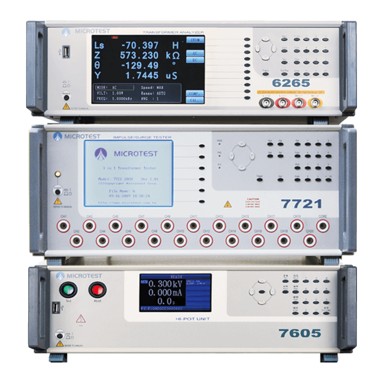
- Page 1 3 in 1 Transformer Testing System 626X+7721+7605 User Manual Ver. 1.01 September-2020...
- Page 2 All brands and trademark are the properties of Microtest Co., Ltd. Microtest Co., Ltd. and its affiliates shall not be liable for the damage, losses or costs incurred due to the accidental use, misuse or abuse by the product buyer or the third party;...
-
Page 3: Table Of Contents
Contents Chapter 1 Notes ......................... 6 Safety Signs ......................... 6 Electrification and Electric Shock ................6 Grounding ........................6 Power .......................... 7 Warm Up ........................7 External control unit ....................7 Machine Malfunction ....................8 Ending the test ......................8 Placement and Storage .................... - Page 4 3.3.4 Rdc Setting ......................30 3.3.5 Turn Ratio Test Setting ..................34 3.4.6 Capacitance Testing Setting ................... 37 3.3.7 Balance Test Setting ....................41 3.3.8 Pin Short Test Setting ..................... 42 3.3.9 Correction Setting ....................43 3.3.10 Complete Deviation Setting ................. 44 Test Mode .........................
- Page 5 4.3.4 Surge(L/S) ......................65 4.3.5 Wire ........................69 4.3.6 L, Lk, Rdc, TR, C ....................70 4.4 File ..........................70 4.4.1 Load ........................71 4.4.2 New ........................71 4.4.3 Save as ........................72 4.4.4 Delete ........................72 4.5 Statistics(Stat) ........................ 73...
-
Page 6: Chapter 1 Notes
Chapter 1 Notes This instrument is not suitable for outdoor use, especially in humid or highly dusty locations. Improper use of this instrument may result in electric shocks. Please read the safety descriptions carefully before using this tester in order to avoid improper or wrongful use and causing accidents. 1.1 Safety Signs Caution: Please read the content of this Manual carefully. -
Page 7: Power
1.4 Power 6265/ 6266/ 6267: Power cables that comply with the local country specifications must be used, and connectors applicable to IEC320 connectors must be used for the connection of this instrument. Users must ensure that the ground cable is properly grounded. If a fuse is included in the power plug, use fuses that comply with 0.8 ampere safety regulations. -
Page 8: Machine Malfunction
1.7 Machine Malfunction If the tester malfunctions, such as the voltage displayed on the voltmeter differs greatly from the voltage set, or that the high voltage output warning light remains on though there is no high voltage output, etc., please stop using this machine immediately and contact our company or your dealer for repairs.1.7 Test End Please turn off the power switch when this tester is not in use. -
Page 9: Static
If the instrument presents any Tolerance sign, do not attempt to dismantle it for making repairs; instead, send the instrument to our professional maintenance personnel for solving the problem. 1.12 Static This instrument uses components that are very sensitive to static. ... - Page 10 7721 Impulse winding Tester 21 channels. Programmable impulse voltage, low-energy detection without damaging the DUT. Built-in storage 200 sets testing waveform. Storage golden sample (DUT) standard waveform in the instrument, and compare with the other sample waveform. ...
-
Page 11: Package And Accessories
2.2 Package and Accessories Standard accessories included: Power Cord * 3 User Manual (CD) * 1 Scan Box (F7721) * 1 HV Test Cable * 21 25Pin-25Pin Cable * 1 Remote Control Cable * 1 ... -
Page 12: Rear Panel
Monitor: This is where the test results are displayed. Soft keys: These keys will be used when you select the functions on the right side of the display. Number keys: Entering numbers when editing. Function keys: There are Sys, Func, Set, File, Stat, Enter, Exit and Test keys. -
Page 13: Fixture F7721
Voltage Selector: Please confirm whether the input voltage is 110V or 220V before connecting the plug, and switch the Voltage Selector to the proper voltage position (110V/220V). GND: Grounding terminal. F7721 Remote: Use 25P-25P cable to connect between 7721 and fixture F7721. -
Page 14: Setting Process
Control key: Press start and stop key to control the system and the result will show by Green (For pass) and Red (For Fail) LED. Channels: CH1~CH20 to connected with CH1~CH20 channels on 7721. Remote control: To connected with EXT.I/O on 626X. - Page 15 SYSTEM: Enters the system setting screen (System Setup). METER: Enters the meter measurement mode (Meter Mode). TRANS: Enters the transformer test setting function screen (Transformer Setting Menu). FILE: Enters the file management screen (File Management).
-
Page 16: System Setup (System)
3.2 System Setup (SYSTEM) Press the Menu control key to enter the Main Menu screen, and then select SYSTEM to enter the system setting screen. Figure 3-2-1 System Setup (1/3) screen Trigger delay (mS): Sets the trigger delay time; the setting range is 0~5000 and the unit is mS. - Page 17 Handler Interface: Sets Handler Interface function ON/OFF; the Select function key can be used to make selections. ON: Enables the Handler Interface function. OFF: Disables the Handler Interface function. Edit Lock:Edit lock function, if there is a password, it will prompt to enter the password, and the setting value can be changed after confirming the old password.
- Page 18 Figure 3-2-2 System Setup (2/3) screen Rescan Interval (x100mS): Sets the time for continual test and continual test intervals in transformer test mode; the setting range is between 0~100. When the value is set as 0, the continual test function is disabled. ...
- Page 19 12. Upload Test Data: Sets whether to turn the data upload function ON/OFF under transformer test mode. ON: Enables the test data upload function. When the test is complete, the test data will be automatically uploaded through the communication port (RS-232/LAN) set.
- Page 20 Figure 3-2-3 System Setup (3/3) screen 17. Handler Interface Mode:Use the select function key to set the output signal of Handler Interface are “Pass” or “Fail” in the both of test mode and multi-DUT mode. PASS:Will output when each DUT test result is "Pass". ...
- Page 21 Figure 3-2-4 LAN Setup screen Auto IP: Sets whether to acquire IP automatically or configure manually. DHCP: Acquire available IP address automatically though the DHCP server. When this setting is used, no other fields need to be set, and ※...
- Page 22 Figure 3-2-5 Set P/W 20. Set P/W:Set password function to avoid the Edit Lock function can be modifying arbitrarily. The following sets the password according to different situations: Set new password: This state is that you never set the password, if you want to select the password, please follow the steps as below, Enter new password >>...
-
Page 23: Transformer Setting Menu
3.3 Transformer Setting Menu Press the Menu control key, the screen will display the Main Menu; then press Trans to enter the transformer setting menu. This is where the various transformer test items can be edited. Figure 3.3.1 Transformer Setting Menu screen 3.3.1 WINDING/FIXTURE Setting WINDING/FIXTURE: Transformer winding setting/Transformer and fixture pin allocation. - Page 24 Fixture Channel: Configures the position where each transformer pin is inserted on the fixture terminal; set using the number keys. DUT No.:Multi DUT can be set by 1~12 with number keys. When the test DUT more than one then you can use different number to distinguish the DUT. Allocate: Automatic transformer pin allocation;...
-
Page 25: Test Sequence Setting
3.3.2 Test Sequence Setting Test Sequence Setting: Sets the test order of each item / whether to test each item. Figure 3.3.4 Allocate Pin to Fixture screen Test Sequence Setting: : Changes test order, it moves the currently selected test item up/down by one slot. -
Page 26: L/Lk/Q/Rac/Z/D/Θ/X/Y Setting
3.3.3 L/Lk/Q/Rac/Z/D/θ/X/Y Setting L/Lk/Q/Rac/Z/D/θ/X/Y Setting: Ls (serial inductance), Lp (parallel inductance), Lk (leaking inductance), Q (quality factor), Rs (serial resistance), Rp (parallel resistance), Z (impedance), D (dissipation factor), θ (phase angle), X (reactance), Y (admittance) test item settings; the screen is as shown below. Figure 3.3.5 Ac test item setting L/Lk/Q/Rac/Z/D/θ/X/Y setting description: Wind: Transformer coil winding setting field;... - Page 27 use of this compensation value is confirmed, this error value will be compensated automatically during testing. (Put the DUT in place before measuring.) Back: Exits this function screen. Para: Test item field; test items displayed by the function keys to the right of the screen can be selected, as shown in the figure below: Figure 3.3.6 Ac test parameter The software key (Para) to the right of the screen can be used to switch between...
- Page 28 Figure 3.3.7 Ac test item Measure Meas function software key description: Accept: Confirm the use of this measured value as the standard value and return to the edit screen. Back: Do not use the current measured value and return to the edit screen. ...
- Page 29 Ls: Test parameter and measured value display field; this value is the actual measured value. STD: Standard value display field; this is the standard value set for this test item. DEVI: Deviation value display field; it is the difference between the standard value (STD) set and the current measured value.
-
Page 30: Rdc Setting
Rate: Measurement speed setting field; four measurement speeds are available for selection: MAX/FAST/MED/SLOW. Figure 3.3.10 Bias & Dly Bias: DC Bias Current function; the setting range is between 0~100mA. This function must be used with fixtures equipped with the DC Bias Current function (optional purchase). - Page 31 Rdc setting description: Wind: Transformer coil winding setting field; select the Wind function key to the right to enter settings. Right function keys descriptions: Wind: Press this function key to select previously edited coil winding. Meas: Measurement key; fixtures can be used to measure the value of the DUT for this item, and you can choose whether to carry over this measured value to be used as the standard value for this test item.
- Page 32 Figure 3.3.12 Rdc measure Meas function software key description: Accept: Confirm the use of this measured value as the standard value and return to the edit screen. Back: Do not use the current measured value and return to the edit screen.
- Page 33 Rdc: Test parameter and measured value display field; this value is the actual measured value. STD: Standard value display field; this is the standard value set for this test item. DEVI: Deviation value display field; it is the difference between the standard value (STD) set and the current measured value.
-
Page 34: Turn Ratio Test Setting
3.3.5 Turn Ratio Test Setting Turn Ratio Test Setting: ※ It is strongly recommended that when editing this step, place windings with more coils at the initial end and the windings with fewer coils at the secondary end in order to prevent forced amplification of the signal and generating a voltage that is too high, exceeding the measurement range acceptable to the instrument. - Page 35 Devia: Compensation function; fixtures can be used to measure the value of the DUT for this item, the system will calculate the deviation between this measured value and the standard value of this item automatically. When the use of this compensation value is confirmed, this error value will be compensated automatically during testing.
- Page 36 entry and automatically add the compensation value when testing this item. The screen is as shown below: Figure 3.3.17 Turn ratio deviation Devia function description: Rdc: Test parameter and measured value display field; this value is the actual measured value. ...
-
Page 37: Capacitance Testing Setting
Max, Min: Sets the upper and lower limit field; the value can be entered directly or use the % key to perform settings. In the Limit Setting window, enter the percentage values for the upper and lower limit respectively; after pressing the Enter key, the system will automatically carry of the value to the Max and Min fields. - Page 38 Figure 3.3.19 Capacitance setting Capacitance test setting description: Pin+, Pin-: Sets the pin of the transformer to measure the capacitance value. Right function keys descriptions: Meas: Measurement key; fixtures can be used to measure the value of the DUT for this item, and you can choose whether to carry over this measured value to be used as the standard value for this test item.
- Page 39 Std: Sets the standard value; the following three input methods can be used: Enter the value using the number keys directly. Press the Meas function key to the right to acquire the measurement value to use as the standard value directly, as shown in the figure below: Figure 3.3.20 Capacitance measure Meas function software key description: ...
- Page 40 Figure 3.3.21 Capacitance deviation Devia function description: C: Test parameter and measured value display field; this value is the actual measured value. STD: Standard value display field; this is the standard value set for this test item. DEVI: Deviation value display field;...
-
Page 41: Balance Test Setting
Figure 3.3.22 Capacitance limit setting Rate: Measurement speed setting field; four measurement speeds are available for selection: MAX/FAST/MED/SLOW. Dly: Delay time setting field; the setting range is between 0~9999mS. 3.3.7 Balance Test Setting Balance Test Setting: Coil balance test item settings; it can compare the measured values of two sets of windings under the same conditions (test item/test frequency/test voltage). -
Page 42: Pin Short Test Setting
Wind: Press this function key to select previously edited coil winding. Copy: Copy this set of test item to the next set. Delete: Deletes this set of test item. Back: Exits this function screen. Para: Test item field; the software key (Para) to the right of the screen can be used to switch between test items, which include the Ls, Lp, Lk, Rs, Z, and DCR etc. -
Page 43: Correction Setting
3.3.9 Correction Setting Correction: Fixture error correction test; the goal for the correction is to eliminate the errors caused by parasitic capacitance or serial impedance of the fixture or test cable. The corrected and reset data will be saved in the flash memory inside the instrument; the data will not disappear even if powered off. -
Page 44: Complete Deviation Setting
3.3.10 Complete Deviation Setting Complete Deviation: Uses GOLDEN SAMPLE as the standard to perform error compensation setting; it compensates the measured value to the value acknowledged by you. Figure 3.3.26 Complete deviation setting screen Complete deviation setting description: ※This compensation setting requires placing the GOLDEN SAMPLE in the F5220 test fixture. - Page 45 Figure 3.3.27 deviation setting screen START: Starts performing test and calculate the compensation value; tests will be performed individually based on the test items you created. This test value will use standard value of the test item you created as the basis to perform compensation to the standard value.
-
Page 46: Test Mode
3.4 Test Mode When you have finished editing the step, the Test key on the front panel can be pressed to enter test mode, and use the Trigger key to perform transformer test; its test screen functions and definitions are as shown in the figure below: Figure 3-4-1 Multi Step Mode screen ※The maximum value of the PASS/FAIL statistics is 999,999,999 each. -
Page 47: File Management
3.5 File Management Under the Main Menu screen, press the FILE function key to enter the file management main menu. Figure 3-5-1 FILE MANAGEMENT screen 3.5.1 Loading File The figure below is the RAM FILE (internal file list) screen; the directional keys can be used to select the file to load. -
Page 48: Saving As
Figure 3.5.3 USB FILE screen RAM File: Returns to the internal file list screen. Copy to RAM: Copies the currently selected file from the USB flash drive to the internal storage of the machine. All to RAM:Copy all the file to the internal storage of the machine. ※... -
Page 49: Creating New File
Figure 3.5.4 SAVE AS screen Filename: File name input area. OK: Save file confirm key. Select: File name text selection confirm key. Clear: File name deletion key; the letter at the end will be cleared each time it is pressed. -
Page 50: Deleting File
Filename: File name input area. OK: Save file confirm key. Select: File name text selection confirm key. Clear: File name deletion key; the letter at the end will be cleared each time it is pressed. QUIT: Returns to the file management page. -
Page 51: Chapter 4 7721 Function Setting
Chapter 4 7721 Function Setting Note: 7721 settings include settings of 7605. 4.1 System Setup Menu (Sys) Press the Sys control key and the screen will enter the System Setup Menu screen. Figure 4.1 System Setup Menu screen 4.1.1 System Setup ... -
Page 52: Test Configuration
confirming the old password. Locked: Enable the Key Lock function. Unlocked: Disable the Key Lock function. ※If you want to set/change password, you can set it on “4.1.4 Password”. LCD contrast: To sets the LCD contrast 1 ~ 8. ... - Page 53 key can be used to make selections. ALL: Prompt is enabled whether the test result is PASS/FAIL. Enable prompt only when the test result is PASS. Enable prompt only when the test result is FAIL. OFF: Disable prompt. Test data font: To sets the font display large/small. Large: Test mode font display Large.
-
Page 54: Date & Time
Off: Disable upload test data function. Trigger delay: To sets the Trigger delay time 0~2500mS. Lock fixture if fail: To sets the Lock fixture if fail function Yes/No. Yes: Enable the function. No: Disable the function. 4.1.3 Date & Time Figure 4.1.3 Set Time screen ... -
Page 55: Password
4.1.4 Password Figure 4.1.4-1 Set new password screen Set password(New PSW): Sets the New password Figure 4.1.4-2 Confirm password screen Set password(Confirm): Enter the new password again. -
Page 56: Function Menu (Func)
Figure 4.1.4-3 Check password screen Check Password: Enter the Password. 4.2 Function Menu (Func) Press the Func control key and the screen will enter the Function Menu screen. Figure 4.2 Function Menu screen... -
Page 57: Self-Test
4.2.1 Self-test Figure 4.2.1 Self-test screen CPU: To check the CPU is connected. RAM: To check the RAM is connected. ROM: To check the ROM is connected. EEPROM: To check the EEPROM is connected. CLOCK: To check the CLOCK is connected. -
Page 58: Surge Voltage Calibration
4.2.2 Surge voltage calibration This function requires a high-voltage meter to calibration the voltage. Figure 4.2.2 Surge voltage calibration screen Up: To increase code value. Down: To reduce the code value. Done: To save the setting values. ... -
Page 59: Surge Voltage Test
4.2.3 Surge voltage test This function requires a high-voltage meter to check the voltage. Figure 4.2.3 Surge voltage test screen On: Turn on the H/V output. Off: Turn off the H/V output. Up: To increase the SET voltage value. ... -
Page 60: Test Setting Menu (Set)
Firmware version: The current firmware version. Released date: The date of released date. Total file space: The total files you can create in this model. Free file space: The number of files you can create currently. 4.3 Test Setting Menu (Set) Press the Set control key, the screen will display the Test Setting Menu. - Page 61 Sequence: Sets the test order of each item / whether to test each item. Fixture: Sets the transformer and fixture pin allocation. 4.3.1.1 Sequence Figure 4.3.3 Test Sequence Setting screen Forward/ Backward: Changes test order, it moves the currently selected test item up/down by one slot.
-
Page 62: Insulation
4.3.1.2 Fixture Figure 4.3.4 Transformer pin VS Fixture channel screen Mapping: Automatic transformer pin allocation; after entering the two parameters below and pressing the ENTER key, the corresponding pins of the transformer and fixture will be set automatically. Clr.: Clears the single setting. -
Page 63: Hipot Test Setting
Exit: Return to the previous screen. H/V Pin+: This item sets up the high voltage Pin+ output channel. There are 20 options for you to set as desired. Select the channel number in the H/V Pin+ set it as the high voltage channel, not selected represent closed channels. ... - Page 64 Copy: Copy the previous setting to next setting. Del.: Delete the current setting. Exit: Return to the previous screen. H/V Pin+: This item sets up the high voltage Pin+ output channel. There are 20 options for you to set as desired. Select the channel number in the H/V Pin+ set it as the high voltage channel, not selected represent closed channels.
-
Page 65: Surge(L/S)
4.3.4 Surge(L/S) Figure 4.3.9 Impulse (Surge) Test Setting Figure 4.3.10 Pin Prog Prog: Selects the test pin of Surge test. Learn: To learn the wave of product. Para: To sets the parameter. Copy: Copy the previous setting to next setting. ... - Page 66 4.3.4.1 Learn Zoom in Zoom out Figure 4.3.11 Learn Screen Trig: To start learning. Zoom in: To zoom in the wave that at least have one complete cycle. Zoom out: To zoom out the wave that at least have one complete cycle. ...
- Page 67 Area size: Its test looks for a change in the area under the waveform but does not take into account any distortion or movement of the waveform. ※ The test range can use the software key T1(T1→ ,T1←) and T2(T2→ ,T2←) to set.
- Page 68 ※ The test range can use the software key T1(T1→ ,T1←) and T2(T2→ ,T2←) to set. Figure 4.3.17 Flutter value Figure 4.3.18 Sets the Flutter test range Wave comp: Its looks for a change in the waveform voltage or frequency. ※...
-
Page 69: Wire
Figure 4.3.21 Corona setting screen 4.3.5 Wire Figure 4.3.22 Wire test setting Del.: Delete the current setting. Exit: Return to the previous screen. Step: Test step; a maximum of 12 short-circuit test items can be edited. Pin+/Pin-: Sets the test pin combinations for the short-circuit test. -
Page 70: L, Lk, Rdc, Tr, C
4.3.6 L, Lk, Rdc, TR, C Figure 4.3.23 LCR, TF Test setting screen This function is to setting the transformer tester(626X,623X series). Exit: Return to the previous screen. 4.4 File Press the File control key, the screen will display the File management menu . Figure 4.4.1 File management menu... -
Page 71: Load
4.4.1 Load Figure 4.4.2 Load file screen Load: To load file. Select the file that you need the press LOAD. Exit: Return to the previous screen. 4.4.2 New Figure 4.4.3 Create new file screen Ok: After naming, press OK to save the file name. ... -
Page 72: Save As
4.4.3 Save as This function is to copy the file and save under another name. Figure 4.4.4 Save as screen Ok: After naming, press OK to save the file name. Sel.: To select the name. Clr.: To clear the selected name. ... -
Page 73: Statistics(Stat)
4.5 Statistics(Stat) Figure 4.5.6 Statistics screen(1/3) Figure 4.5.7 Statistics screen(2/3) Qty.rate: To change the display method, number or percentage. Clr.: To clear all the statistics data. Figure 4.5.7 Statistics screen(3/3) Tested: Shows how many times have been tested. ... - Page 74 MICROTEST 14F-6, No.79, Sec.1 Xintai 5 Rd., Xizhi Dist., New Taipei City 221, Taiwan, R.O.C. Tel: +886-2-2698-3877 Fax: +886-2-2698-4089 E-mail: sales@microtest.com.tw...
Need help?
Do you have a question about the 626 Series and is the answer not in the manual?
Questions and answers