Advertisement
Quick Links
IP Control - Quick Start Guide
1. Introduction
To take advantage of the full range of features, we recommend y
User Guide after performing the Quick Start procedure. It's in P
supplied CD or on our website www.minicom.com in the Support
The IP Control extends your KVM (keyboard, video, mouse) fro
server over TCP/IP via LAN, WAN or Internet connection. Now
monitor and manage your servers from wherever you are, inside
organization. The IP Control is a cost-effective hardware solution,
remote KVM access & control of a computer/server from the BIO
independent of the OS. It is designed to connect to a single computer
switch to control multiple servers, over TCP/IP communication.
2. System components
The IP Control system consists of:
•
1 IP Control (p/n
1SU70017)
•
1 KVM cable (p/n
5CB00565)
•
1 RS232 cable (p/n
5CB00566)
•
1 Universal power adapter (p/n
•
Rack mount set (p/n 5AC00297)
QUICK START GUIDE
5. Rack mounting the IP Control
The IP Control comes with screw holes on the side for easy rack
figure below.
Screw holes for bracket
Figure 3 Screw holes for rack mounting
Use the L-shaped brackets and screws provided to mount the IP
rack or under a table top as illustrated below. The length of the screws
connecting the brackets to the IP Control unit must not exceed 5
Screw L-shaped
brackets to 1 or both
sides of the unit
Figure 4 Connecting the L-shaped bracket
Figure 5 Connected to a rack
All manuals and user guides at all-guides.com
1111 W. 35th Street, Chicago, IL 60609 USA
1111 W. 35th Street, Chicago, IL 60609 USA
www.tripplite.com/support
www.tripplite.com/support
Copyright ©2012 Tripp Lite. All rights reserved.
Copyright ©2012 Tripp Lite. All rights reserved.
you read the softcopy
PDF format on the
Support section.
om any computer or
Now you can control,
inside or outside the
solution, for secure
IOS level -
puter or to a KVM
nication.
5PSB0005)
rack mounting, see
Control on a server
screws used for
5 mm.
Figure 6 Connected to
o a table top
2
IP C
IP CONTROL
The RS232 cable connects the IP Control
Control to Serial manageable devices such as
Power Management units, routers, etc.
etc.
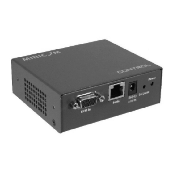
3. The IP Control unit
Figure 1 illustrates the front panel of
Key
yboard
LAN
LAN (Etherne
hernet)
connector
Figure 1 IP
IP Control ports – side 1
For (optional) local access to the connec
connected computer you connect a keyboard,
monitor and mouse to the above KVM
M ports. Connect the IP Control to a 10/100
Mbit Ethernet using the LAN port.
KVM In
KVM In
Connect a computer or KVM switch to
cable. You press the Go Local button
button to disconnect the remote session and access
the computer locally.
Connect an RS232 device to the Serial
erial port using the RS232 cable.
4. Pre-installation guidelines
guidelines
Place cables away from fluorescent ligh
lights, air conditioners, and machines that are
likely to generate electrical noise.
IP C
IP CONTROL
6. Terminology
Below are some terms and their meanings
anings used in this guide.
Term
Meaning
Target server
The computer
uters/servers that are accessed remotely via the IP
Control.
Client computer
The PC run
Remote Session
The process
ss of accessing and controlling Target Servers
connected
cted to IP Control from a User workstation
7. Client computer operat
Windows 2000 or higher, with Firefox
ox 3 or Internet Explorer 6.0 or later version.
Linux with Firefox 3. 128 bit encryption
encryption support is required.
8. Connecting the system
stem
Connect the Target Server / KVM swit
switch to the IP Control as follows:
1. Connect the single connector of the
the KVM cable to the KVM In port of the IP
Control.
2. Connect the other end of the KVM
KVM cable to the KVM ports of the Target Server
/ KVM switch.
3. Connect a Network cable to the IP
IP Control LAN port and to an Ethernet port on
your Network switch.
4. Connect the power adapter.
Figure 7 and Figure 8 illustrate the connections
connections to a computer and KVM switch
respectively, with the optional KVM
the IP Control.
Monitor
Mouse
Go Local
Serial
button
Power
Serial
Go Local
3.3V/2A
Power
Power
LED
Figure 2 IP Control ports – side 2
to the KVM In port using the 1 to 3 CPU
1
nning a remote IP Control session
ting system
console.
3
Advertisement

Related Manuals for Minicom TRIPP-LITE IP Control


Summary of Contents for Minicom TRIPP-LITE IP Control
- Page 1 User Guide after performing the Quick Start procedure. It’s in P PDF format on the Mbit Ethernet using the LAN port. supplied CD or on our website www.minicom.com in the Support Support section. Go Local Serial...
- Page 2 COMPUTER 1 COMPUTER 2 COMPUTER 3 COMPUTER 4 KVM cable MINICOM MINICOM Pr oL ia n t D L3 6 0 9.1 - G B 1 0 k 9.1 - GB 1 0 k ULT R A 2 S C SI...
Need help?
Do you have a question about the TRIPP-LITE IP Control and is the answer not in the manual?
Questions and answers