Advertisement
Quick Links
S
olar thermal SyStem
0244EN June 2016
C
ontrol unit
KtD
Description
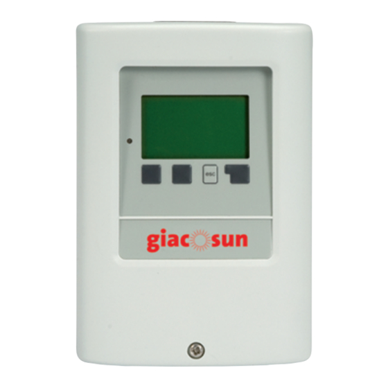
The KTD control unit is used to programme and control a solar thermal systems.
Two different versions are available, KTD3 and KTD5, which are used in
combination with R586S, R586S-0 and R586S-1 circulation groups.
The control unit is user-friendly thanks to its backlight graphic display, four
buttons, handy programming assistant and on-line help pages.
The KTD control unit has inputs for temperature probes type Pt1000, a relay
output for controlling an electronic circulator, and one or two relay outputs
for commanding a electronic circulator (predisposition for commanding
circulator by PWM or 0-10 V signal) and one or two relay outputs for other
additional functions.
The programs on the control unit allows to set various system configurations.
Operation control functions range from the mere reading of the current
measured values to long-term system monitoring and analysis by means of
charts and statistics. Numerous other functions complete the possibilities
offered by the KTD control unit:
• at any time, you can reset the previous values or, if necessary, the
manufacturer's default values;
• the menu locking function prevents any unwanted modification of the
operating parameters set during the unit programming phase;
• the anti-lockout function activates the pump or valve connected to the relay
for 5 seconds, at regular intervals, to prevent any possible lockout due to a
lengthy period of non-use;
• the anti-legionella function heats the boiler to a high temperature at fixed
time intervals.
The KTD allows also to view the thermal energy level produced by the solar
thermal system thanks to the setting of certain additional parameters (e.g.
glycol type and percentage, and system flow rate).
Versions and product codes
N° of input for tempe-
Serie
Product code
KTD3
KTD3Y003
KTD5
KTD5Y006
Optionals
• KTDPY001: overvoltage protection
• KTDSY001: temperature probe Pt1000 (180 °C)
KTD
N° of included tempe-
rature probe
rature probe
3
3
6
4
Technical data
• Operational room temperature range: 0÷40 °C
• Operational room humidity range: max. 85 %
• Supply voltage: 100÷240 Vac
• Frequency: 50÷60 Hz
• Power consumption: 0,5÷2,5 W (low consumption in standby)
• Pt1000 probes easuring range: -40÷300 °C
• Power outputs: - mechanical relay: 460 VA resistive / 460 W inductive
- electronic relay: 5÷120 W inductive
• Output to control the ErP circulator: - PWM frequency 1 kHz, level 10 V
• Internal fuse: 2 A / 250 V slow blow
• Protection degree: IP40
• Protection class: II
Main characteristics
• Outputs 0-10 V / PWM to control the ErP circulator
• Casing: in 2 parts, ABS
• Type of installation: integrated in the circulation groups (R586S, R586S-0,
R586S-1) or separate on the wall
• Display: graphic display, 128 x 64 points
• Signalling: 1 multi-colour LED
• Programming: 4 buttons
• 18 languages selectable
• Guided installation
• Compliance: - Low voltage 2006/95/EC
- Electromagnetic Compatibility Directive 2004/108/EC
Operating characteristics
Functions
Inputs for Pt 1000 probes
Pt1000 probes supplied
Relays outputs:
- mechanical relay
- electronic relay
Number of system configuration
Measurement of thermal energy
Measurement of thermal energy via VFS sensor
Times and temperat. controlled by thermostat function
Anti-legionella protection via solar system
Anti-legionella protection via auxiliary heat generator
Anti-freezing protection
Net communication
Additional function for not used relays
• Solar By-pass
• Back-up heating control
• Solar panel cooling
• Increase the return flow
• Anti-legionella function
• Tank transfering
• Universal ΔT
• Thermostat 2
• Control of solid fuel boiler
• Signalling with activated protective function
• Signalling with new information message
• Pressure monitoring
• Booster for fast start-up of the system
• Heating circuit
• Parallel operation with R1
• Parallel operation with R2
- 0-10 V tollerance 10 %, for load 10 KΩ
KTD3
KTD5
3
6
3
4
2 (R1 - R2)
1 (R3)
-
2 (R1- R2)
27
42
SI
SI
NO
SI (x 2)
SI
SI
SI
SI
SI
SI
SI
SI
CAN Bus
CAN Bus
1
Advertisement

Summary of Contents for Giacomini KTD3
- Page 1 The KTD control unit is used to programme and control a solar thermal systems. • Type of installation: integrated in the circulation groups (R586S, R586S-0, Two different versions are available, KTD3 and KTD5, which are used in R586S-1) or separate on the wall combination with R586S, R586S-0 and R586S-1 circulation groups.
- Page 2 • fast red flashing if there is an error. Using the 4 buttons (3, 4), you can access the various functions of the control Typical application for KTD3 and KTD5 unit. The “esc” button (3) is used to enter or quit the menu; when it is pressed, the control unit asks for confirmation that the modifications must be stored.
- Page 3 0244EN June 2016 ontrol unit Installation Product specification KTD3 Warning. Differential control unit for programming and controlling the operation The installation and programming of the KTD control unit, and the of the solar thermal system. To be used with the R586S, R586S-0 and initial start-up of the solar thermal system, should only be carried R586S-1 circulation group.
- Page 4 For additional information please check the website www.giacomini.com or contact the technical service: ' +39 0322 923372 6 +39 0322 923255 * consulenza.prodotti@giacomini.com This pamphlet is merely for information purposes. Giacomini S.p.A. retains the right to make modifications for technical or commercial reasons, without prior notice, to the items described in this pamphlet.


Need help?
Do you have a question about the KTD3 and is the answer not in the manual?
Questions and answers