Infinity Interlude Series Service Manual
Hide thumbs
Also See for Interlude Series:
- Service manual (41 pages) ,
- Service manual (37 pages) ,
- Service manual (47 pages)

Related Manuals for Infinity Interlude Series


Summary of Contents for Infinity Interlude Series
- Page 1 Interlude Series IL50 L/R Powered Loudspeaker Service Manual Infinity Systems, Inc 250 Crossways Park Dr. Woodbury, New York 11797 REV1 10/2001...
-
Page 2: Table Of Contents
IL50 CONTENTS SPECIFICATIONS …….……………………………………………….3 DETAILED SPECIFICATIONS …………………….…………………4 CONTROLS and CONNECTIONS …………………….….…………6 OPERATION……………………………………..………..…….……..10 BASS OPTIMIZATION SYSTEM……………………….….…………10 MECHANICAL PARTS LIST…………………….……………………12 EXPLODED VIEW ……………………………………….……………13 EXPLODED VIEW OF AMPLIFIER…………………….……………14 SERVICE TIPS……………………………..……………………….…15 TEST SET UP PROCEDURE…………………….…….……………16 IL50 ADJUST BIAS PROCEDURE……………….…………………17 PACKAGING …………………………….………………………….…18 PRINTED CIRCUIT BOARD DIAGRAMS………………..…………19 ELECTRICAL PARTS LIST (120v)…………………….….…………25 INTEGRATED CIRCUIT DIAGRAMS ………………………………31 HI-PASS CROSSOVER SCHEMATIC……………………..……...…….32... -
Page 3: Specifications
IL50 L/R Specifications IL50 L/R Frequency Response: 32Hz - 22,000Hz (±3dB) Recommended Amplifier Power Range 15-150 watts* Subwoofer Amplifier Output: 250 watts (In to 8Ω from 20 Hz - 100Hz with no more than 0.1% THD) Sensitivity: 88dB (2.83V @ 1 meter) Nominal Impedance: 8Ω... -
Page 4: Detailed Specifications
IL50 L/R Detailed Specifications... - Page 5 IL50 L/R Detailed Specifications (Cont.)
-
Page 6: Controls And Connections
IL50 L/R Controls and Connections (Cont.) - Page 7 IL50 L/R Controls and Connections...
- Page 8 IL50 L/R Controls and Connections (Cont.)
- Page 9 IL50 L/R Controls and Connections (Cont.)
-
Page 10: Operation
IL50 L/R Operation/Bass Optimization System... - Page 11 In order to facilitate quicker and more accurate results, Infinity has developed an optional test and measurement kit that allows the user to perform a series of measurements and aids him/her in properly setting the Bass Optimization System controls.
-
Page 12: Mechanical Parts List
IL50 L/R IL50 L/R Mechanical Parts List NOT FOR SALE * On 9/1/2000 a new replacement port tube was included with the IL50. Supplied part number reflects the new part. In addition, modified IL50 product w/ new port tube may be identified by the following serial number prefixes, which appears on the amplifier faceplate and the carton barcode label: IL50BLKL - NM0825-01001 and above... -
Page 13: Exploded View
IL50 L/R Exploded View SCREW, (4) #6X.75" PB PPH BLK 903401-012 SCREW, (4) 6-19X.375 MS PPH BLK 905401-006 PORT TUBE, 336805-001 VOLUME CONTROL See page 12 ASS'Y w/CABLE, 336250-001, R CABINET, 336250-002, L IL50 (NOT FOR SALE) (ROTATED) SCREW, (6) MID RANGE #6X.75"... -
Page 14: Exploded View Of Amplifier
IL50 L/R Exploded View of Amplifier High Level Binding Posts-JC0070 Feature PCB Rear Plastic Cover Linear PCB 930050 RABOS PCB Power Supply EMI Filter Power Cord, 15 FT. WI0043... -
Page 15: Service Tips
IL50 L/R Service Tips... -
Page 16: Test Set Up Procedure
IL50 L/R Test Set Up and Procedure SYSTEM AURAL SWEEP TEST Equipment needed: • Function/signal generator/sweep generator • Integrated Amplifier • Multimeter • Speaker cables General Unit Function (UUT = Unit Under Test) 1. Remove the loudspeaker grille. 2. Switches on the amplifier faceplate: Sub Input to "Line Level"... -
Page 17: Il50 Adjust Bias Procedure
IL50 ADJUST BIAS PROCEDURE (Mandatory when any output MOSFET transistors Q3,4,7,8 are replaced) 1. Amplifier should be unplugged and OFF. 2. Remove Amp assembly from cabinet; remove rear plastic cover if present. All wires exiting the cover can remain connected unless they will prevent you from removing the amplifier or accessing potentiometers on the Linear board PCB in the following steps. -
Page 18: Packaging
IL50 L/R Packaging... -
Page 19: Printed Circuit Board Diagrams
IL50 L/R EMI Filter PCB... - Page 20 IL50 L/R Feature PCB...
- Page 21 IL50 L/R Linear PCB...
- Page 22 IL50 L/R Volume Control PCB...
- Page 23 IL50 L/R Power Supply PCB...
- Page 24 IL50 L/R RABOS PCB...
-
Page 25: Electrical Parts List (120V)
IL50 L/R IL50 Electronic Parts List Part# Reference Designator Description... - Page 26 IL50 L/R IL50 Electronic Parts List (Cont.) Part# Reference Designator Description...
- Page 27 IL50 L/R IL50 Electronic Parts List (Cont.) Part# Reference Designator Description...
- Page 28 IL50 L/R IL50 Electronic Parts List (Cont.) Part# Reference Designator Description...
- Page 29 IL50 L/R IL50 Electronic Parts List (Cont.) Part# Reference Designator Description...
- Page 30 IL50 L/R IL50 Electronic Parts List (Cont.) Part# Reference Designator Description...
-
Page 31: Integrated Circuit Diagrams
IL50 L/R Integrated Circuit Diagrams... -
Page 32: Hi-Pass Crossover Schematic
IL50s Crossover Network Schematic... -
Page 33: Il50 Schematics
IL50s Feature Main Schematic... - Page 34 IL50s Feature Main Schematic (Cont.)
- Page 35 IL50s Linear PCB Schematic...
- Page 36 IL50s 250W Domestic Main Power Supply Schematic...
- Page 37 IL50s Feature RABOS Schematic...
- Page 38 IL50s Interlude Volume and EMI Filter Schematic...
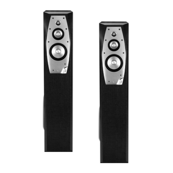
- Page 39 NFINITY NTERLUDE ESIGNED WITH YOUR HOME IN MIND Infinity offers a choice of grille colors to ensure that your new Interlude loudspeaker system will make a distinctive design statement in your home. To order, call 1.800.553.3332 or visit our Web site at www.infinitysystems.com.
Need help?
Do you have a question about the Interlude Series and is the answer not in the manual?
Questions and answers