Infinity Interlude Series Service Manual
Powered loudspeaker
Hide thumbs
Also See for Interlude Series:
- Service manual (41 pages) ,
- Service manual (37 pages) ,
- Service manual (39 pages)

Subscribe to Our Youtube Channel
Related Manuals for Infinity Interlude Series


Summary of Contents for Infinity Interlude Series
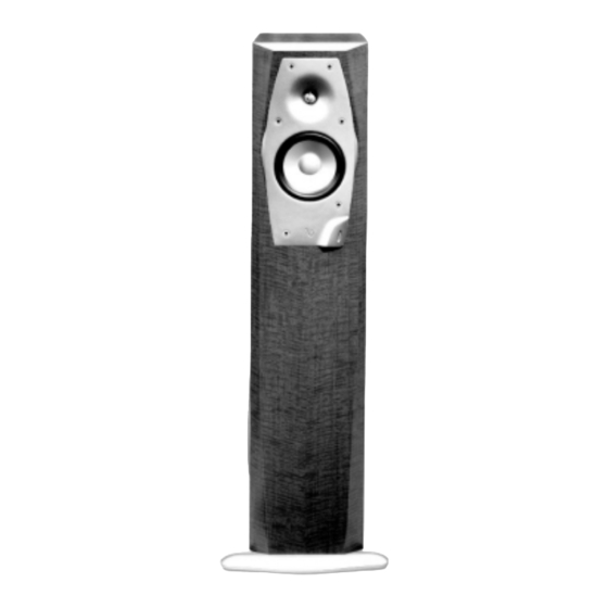
- Page 1 Interlude Series IL50 L/R Powered Loudspeaker Service Manual Infinity Systems, Inc 250 Crossways Park Dr. Woodbury, New York 11797 REV10 10/2005...
-
Page 2: Table Of Contents
IL50 CONTENTS SPECIFICATIONS …….……………………………………………….3 DETAILED SPECIFICATIONS …………………….…………………4 CONTROLS and CONNECTIONS …………………….….…………6 OPERATION……………………………………..………..…….……..10 BASS OPTIMIZATION SYSTEM……………………….….…………10 MECHANICAL PARTS LIST…………………….……………………12 EXPLODED VIEW ……………………………………….……………13 EXPLODED VIEW OF AMPLIFIER…………………….……………14 SERVICE TIPS……………………………..……………………….…15 SERVICE BULLETIN INF2002-02 ……………………..……………16 SERVICE BULLETIN INF2001-04 ……………………..……………17 SERVICE BULLETIN INF2002-05 ……………………..……………19 TECH TIP INFTT2003-03……………………………………………..24 TEST SET UP PROCEDURE…………………….…….……………25 IL50 ADJUST BIAS PROCEDURE……………….…………………26 PACKAGING …………………………….………………………….…27... -
Page 3: Specifications
IL50 L/R Specifications IL50 L/R Frequency Response: 32Hz - 22,000Hz (±3dB) Recommended Amplifier Power Range 15-150 watts* Subwoofer Amplifier Output: 250 watts (In to 8Ω from 20 Hz - 100Hz with no more than 0.1% THD) Sensitivity: 88dB (2.83V @ 1 meter) Nominal Impedance: 8Ω... -
Page 4: Detailed Specifications
IL50 L/R Detailed Specifications... - Page 5 IL50 L/R Detailed Specifications (Cont.)
-
Page 6: Controls And Connections
IL50 L/R Controls and Connections (Cont.) - Page 7 IL50 L/R Controls and Connections...
- Page 8 IL50 L/R Controls and Connections (Cont.)
- Page 9 IL50 L/R Controls and Connections (Cont.)
-
Page 10: Operation
IL50 L/R Operation/Bass Optimization System... - Page 11 In order to facilitate quicker and more accurate results, Infinity has developed an optional test and measurement kit that allows the user to perform a series of measurements and aids him/her in properly setting the Bass Optimization System controls.
-
Page 12: Mechanical Parts List
IL50 L/R IL50 L/R Mechanical Parts List NOT FOR SALE * On 9/1/2000 a new replacement port tube was included with the IL50. Supplied part number reflects the new part. In addition, modified IL50 product w/ new port tube may be identified by the following serial number prefixes, which appears on the amplifier faceplate and the carton barcode label: IL50BLKL - NM0825-01001 and above... -
Page 13: Exploded View
IL50 L/R Exploded View SCREW, (4) #6X.75" PB PPH BLK 903401-012 SCREW, (4) 6-19X.375 MS PPH BLK 905401-006 PORT TUBE, 336805-001 VOLUME CONTROL See page 12 ASS'Y w/CABLE, 336250-001, R CABINET, 336250-002, L IL50 (NOT FOR SALE) (ROTATED) SCREW, (6) MID RANGE #6X.75"... -
Page 14: Exploded View Of Amplifier
IL50 L/R Exploded View of Amplifier High Level Binding Posts-JC0104 Feature PCB Rear Plastic Cover Linear PCB 930050 RABOS PCB Power Supply EMI Filter Power Cord, 15 FT. WI0043... -
Page 15: Service Tips
IL50 L/R Service Tips... -
Page 16: Service Bulletin Inf2002-02
4. Locate the power supply section and R22 from the illustrations below. R22 can be checked in-circuit and should be 100k ohms ±5%. If it is any other value, or open, replace with Infinity part# RC0082. 5. Reassemble the amplifier, rear cover, replace the amplifier in the cabinet and test the subwoofer. -
Page 17: Service Bulletin Inf2001-04
Service Bulletin Service Bulletin INF2001-04 Rev2 – May 2005 Warranty labor rate: MINOR repair All Infinity Service Centers Model: Interlude and Intermezzo IL50, IL60, IL100s, IL120s, IM1.2s, IM4.1t Subject: No Output In the event you receive an Interlude or Intermezzo loudspeaker with the complaint: “There is no output, and the LED on the volume control does not light, red or green”, check the item listed below:... - Page 18 9) If it is 25 volts or greater, turn the amplifier OFF, disconnect from the power source, and replace: IL120S, IL60: Q504,Q507 IRF640 on the Power Supply PCB, Infinity part# QM0015. IL50, IL100s: Q1 IRF540 on the Power Supply PCB, Infinity part# QM0020.
-
Page 19: Service Bulletin Inf2002-05
IL50 Service Bulletin Service Bulletin INF2002-05 Rev5 - October 2005 Warranty labor rate: MAJOR repair All Infinity Service Centers Model: Interlude IL50 Subject: Reliability Upgrade PURPOSE: Improve reliability of the IL50 amplifier; this procedure should be followed for every unit that has to be serviced, for any reason. - Page 20 2W 5% Metal film, not wire wound. If not order Infinity Part# RX0109 Ensure that Q6 is MPS A92 PNP TO92 MPSA92TR. If not order Infinity Part # QB0014 Ensure that R22 is 100K, 1/2 watt part. (Color Code - Brown, Black, Yellow and Gold), RES, CF 100K 1/2W 5%.
- Page 21 IL50 3) IL50 ADJUST BIAS PROCEDURE (Mandatory when any output MOSFET transistors Q3,4,7,8 are replaced) 1. Locate the Linear board assembly (PCB with the output transistors) 2. Adjust R11 and R27 fully Counter Clockwise. See diagram below. 3. Apply 120 VAC power to unit, Turn power switch ON. 4.
- Page 22 IL50 FIGURE 1 POWER SUPPLY BOARD UPGRADE FIGURE 2 LINEAR BOARD UPGRADE (Most components absent for clarity)
- Page 23 IL50 FIGURE 3 LINEAR BOARD UPGRADE (cont’d) A & B Identification ACTION Model STATUS 120V Needs Reliability IL50 No Label Follow Steps Outlined Above Upgrade Small White Rectangular label IL50 Modified by factory NONE REQUIRED On Amp faceplate “Rev II 2002-XXX”...
-
Page 24: Tech Tip Inftt2003-03
2) Clean and repair the PC board if required (See Tech Tip HCG2002-01 - Damaged Printed Circuit Boards). 3) Replace the Hybrid Bash Controller IC: IL50,IL100s,MSW-1,IM2.6,IM3.5c U1 in models: IL60, IL120s U501 in models: Infinity part # HC1011 FAILURE TO FOLLOW THE INSTRUCTIONS ABOVE MAY RESULT IN UNIT FAILURE WHEN THE AMPLIFIER IS POWERED UP... -
Page 25: Test Set Up Procedure
IL50 Test Set Up and Procedure SYSTEM AURAL SWEEP TEST Equipment needed: • Function/signal generator/sweep generator • Integrated Amplifier • Multimeter • Speaker cables General Unit Function (UUT = Unit Under Test) 1. Remove the loudspeaker grille. 2. Switches on the amplifier faceplate: Sub Input to "Line Level"... -
Page 26: Il50 Adjust Bias Procedure
IL50 IL50 ADJUST BIAS PROCEDURE (Mandatory when any output MOSFET transistors Q3,4,7,8 are replaced) 1. Amplifier should be unplugged and OFF. 2. Remove Amp assembly from cabinet; remove rear plastic cover if present. All wires exiting the cover can remain connected unless they will prevent you from removing the amplifier or accessing potentiometers on the Linear board PCB in the following steps. -
Page 27: Packaging
IL50 Packaging... -
Page 28: Printed Circuit Board Diagrams
IL50 EMI Filter PCB... - Page 29 IL50 Feature PCB...
- Page 30 IL50 L/R Linear PCB...
- Page 31 IL50 Volume Control PCB...
- Page 32 IL50 Power Supply PCB...
- Page 33 IL50 RABOS PCB...
-
Page 34: Electrical Parts List (120V)
IL50 IL50 Electronic Parts List Part# Reference Designator Description... - Page 35 IL50 IL50 Electronic Parts List (Cont.) Part# Reference Designator Description...
- Page 36 IL50 IL50 Electronic Parts List (Cont.) Part# Reference Designator Description...
- Page 37 IL50 IL50 Electronic Parts List (Cont.) Part# Reference Designator Description Change R22 to 100K ohm - See Page 16...
- Page 38 IL50 IL50 Electronic Parts List (Cont.) Part# Reference Designator Description...
- Page 39 IL50 IL50 Electronic Parts List (Cont.) Part# Reference Designator Description...
-
Page 40: Integrated Circuit Diagrams
IL50 Integrated Circuit Diagrams... -
Page 41: Hi-Pass Crossover Schematic
IL50s Crossover Network Schematic... -
Page 42: Il50 Schematics
Change R22 to 100K ohm - See Page 16... - Page 43 IL50...
- Page 44 IL50...
- Page 45 IL50...
- Page 47 IL50...
Need help?
Do you have a question about the Interlude Series and is the answer not in the manual?
Questions and answers