Infinity Interlude Series Service Manual
Hide thumbs
Also See for Interlude Series:
- Service manual (41 pages) ,
- Service manual (47 pages) ,
- Service manual (39 pages)

Related Manuals for Infinity Interlude Series


Summary of Contents for Infinity Interlude Series
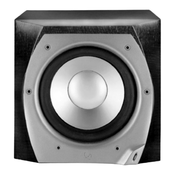
- Page 1 Interlude Series IL120s Subwoofer Service Manual Infinity Systems, Inc 250 Crossways Park Dr. Woodbury, New York 11797 REV 1 10/2001...
-
Page 2: Table Of Contents
IL120s CONTENTS SPECIFICATIONS …….…………………………….………………….3 DETAILED SPECIFICATIONS ……………………..…………………4 CONTROLS and CONNECTIONS ………………….….….…………6 OPERATION……………………………………..……..…..…….……..8 BASS OPTIMIZATION SYSTEM…………….………….….…………9 MECHANICAL/PACKING PARTS LIST………………..……………11 EXPLODED VIEW ……………………………………….……………12 PACKAGING …………………………….………………………….…13 EXPLODED VIEW OF AMPLIFIER…………………….……………14 TEST SETUP and PROCEDURE……………….……..……………15 IL120s ADJUST BIAS PROCEDURE………………..…………………16 PRINTED CIRCUIT BOARD DIAGRAMS………………..…………17 ELECTRICAL PARTS LIST (120v)…………………….….…………23 INTEGRATED CIRCUIT DIAGRAMS ………………………………31 IL120s SCHEMATICS…………..……….……………………………32... -
Page 3: Specifications
IL120s SPECIFICATIONS IL120s Frequency Response: 28Hz - 150Hz (±3dB) Maximum Amplifier Output: 500 watts (20Hz - 150Hz with no more than 0.1% THD) Crossover Frequencies: 50Hz - 150Hz, 24dB/octave, continuously variable Driver: 12" C.M.M.D. Dimensions (H x W x D): 17-1/2"... -
Page 4: Detailed Specifications
IL120s DETAILED SPECIFICATIONS... - Page 5 IL120s DETAILED SPECIFICATIONS (Cont.)
-
Page 6: Controls And Connections
IL120s CONTROL and CONNECTIONS... - Page 7 IL120s CONNECTIONS...
-
Page 8: Operation
IL120s OPERATION... -
Page 9: Bass Optimization System
IL120s BASS OPTIMIZATION SYSTEM... - Page 10 If your dealer does not stock the Bass Optimization System test and measurement kit, you may purchase it directly from Infinity. U.S. residents can visit our Web site at www.infinitysystems.com or call 1-800-553-3332. Canadian residents should contact their dealer or call 1-800-567-3275.
-
Page 11: Mechanical/Packing Parts List
IL120s MECHANICAL/PACKAGING PARTS LIST Description Part Number MECHANICAL IL120s COMPLETE AMPLIFIER ASSY WOOFER, 12”, C.M.M.D., shielded, 3.4 ohms ±10% 336056-001 VOLUME CONTROL, R-IL 336250-001 FRONT BAFFLE 336439-001 PORT TUBE 336799-001 GRILLE CUP (12) 333249-003 GRILLE, GRAY 336441-001 GRILLE, MIDNIGHT BLUE 336441-002 GRILLE, RICH BURGUNDY 336441-003... -
Page 12: Exploded View
IL120s EXPLODED VIEW SCREW, (12) #8 x .75, PB, PPH BLK PORT TUBE (900101-012) (336799-001) CABINET (NOT FOR SALE) VOLUME CONTROL, R-IL SCREW, (2) (336250-001) #6 x .75, PB, PPH, BLK (903401-012) WOOFER, 12" (336056-001) SCREW, (6) #6 x .75, PB, PPH, BLK (903401-012) IL120s AMPLIFIER ASSY... -
Page 13: Packaging
IL120s PACKAGING POWER CORD, RABOS SCREW 120V US-15' DRIVER (336658-115) (335848-002) SURVEY CARD (330033-001) OWNER'S MANUAL IL100S/IL120S (335839-001) PAD, END, TOP (336496-001) WARRANTY CARD (335841-001) GRILLE ASSEMBLY, GRAY, (336441-001) CARTON (336497-001) PAD, END, BOTTOM (336496-002) -
Page 14: Exploded View Of Amplifier
IL120s EXPLODED VIEW OF AMPLIFIER FEATURE BOARD LINEAR BOARD RABOS BOARD POWER SUPPLY BOARD BOARD QUADJACK (JC0052) SWITCH, (4) SPDT TOGGLE (SR0007) BINDING POSTS GOLD (JC0104) ® FUSE HOLDER PANEL MT SEALED (FH0012) ® AC (120V) IEC SOCKET (JC0129) FUSE, 4A 250V 1.25X.25 SLO-BLO (FS0026) SWITCH,... -
Page 15: Test Setup And Procedure
IL120s TEST SETUP and PROCEDURE AC VOLT METER (10V) IL120s UNDER TEST ® SIGNAL AMPLIFIER GENERATOR ® OUTPUT FROM GENERATOR/AMPLIFIER SYSTEM AURAL SWEEP TEST Equipment needed: • Function/signal generator/sweep generator • Integrated Amplifier • Multimeter • Speaker cables General Unit Function (UUT = Unit Under Test) Switches/knobs on the amplifier faceplate: Input Select to “Line”... -
Page 16: Il120S Adjust Bias Procedure
IL120s ADJUST BIAS PROCEDURE (Mandatory when any output MOSFET transistors Q3,4,7,8 are replaced) 1. Amplifier should be unplugged and OFF. 2. Remove Amp assembly from cabinet; remove rear plastic cover if present. All wires exiting the cover can remain connected unless they will prevent you from removing the amplifier or accessing potentiometers on the Linear board PCB in the following steps. -
Page 17: Printed Circuit Board Diagrams
IL120s IL VOLUME RIGHT BOARD... - Page 18 IL120s EMI FILTER BOARD...
- Page 19 IL120s IL FEATURE BOARD...
- Page 20 IL120s IL RABOS BOARD...
- Page 21 IL120s 500W HC BASH POWER SUPPLY...
- Page 22 IL120s IL 500W LINEAR BOARD...
-
Page 23: Electrical Parts List (120V)
IL120s IL120s ELECTRONIC PARTS LIST Part No. Reference Designator Description PCB, FEATURE SEMICONDUCTORS QM0035 JFET, N-CH J111 TO92 TR UA0003 U5,U6 OPAMP, QUAD 14PIN DIL LM324N UA0009 U1,U2 OPAMP, QUAD 14P DIL TL074/084 UA0010 OPAMP, DUAL 8PIN DIL TL082 DS0001 D9,D100,D101,D102,D103, RECT, 100mA 75V SIGNAL 1N4148T D104,D105, D200,D201... - Page 24 IL120s IL120s ELECTRONIC PARTS LIST (Cont.) Part No. Reference Designator Description RM0158 R27,R79 RES, MF 28K0 1/4W 1% RM0171 R31,R203 RES, MF 475K 1/4W 1% RM0188 R106 RES, MF 499R 1/4W 1% RM0205 R17,R18,R22,R23,R32 RES, MF 22K6 1/4W 1% RM0372 RES, MF 5K76 1/4W 1% RM0404 R2,R6...
- Page 25 IL120s IL120s ELECTRONIC PARTS LIST (Cont.) Part No. Reference Designator Description MISCELLANEOUS JH0074 CNCTR, HEADER 8PIN LOCKING .1C PCB, LINEAR SEMICONDUCTORS DS0001 D1,D2,D3,D4,D5,D6,D7,D8,D9,D10,D11 RECT, 100mA 75V SIGNAL 1N4148T QB0017 Q2,Q6 TRANS, NPN 150V 0.6A 2N5551TR QB0018 Q1,Q5 TRANS, PNP 150V 0.6A 2N5401TR QM0015 Q3,Q7 MOSFET, IRF640 TO220AB...
- Page 26 IL120s IL120s ELECTRONIC PARTS LIST (Cont.) Part No. Reference Designator Description MISCELLANEOUS JH0016 CNCTR, HEADER 2PIN .100CTR JH0074 J13,J14 CNCTR, HEADER 8PIN LOCKING .1C MM0025 J9,J10 MISC, PC MT SCREW TERM 6-32 MT0003 TERM, FASTON MALE PCMT 250X032 MT0023 J3,J6 TERM, FASTON MALE PCMT 187X032 MT0036 TERM, FASTON MALE PCMT 205X032...
- Page 27 IL120s IL120s ELECTRONIC PARTS LIST (Cont.) Part No. Reference Designator Description RM0002 R525 RES, MF 10K0 1/4W 1% RM0050 R531 RES, MF 90K9 1/4W 1% RM0070 R528 RES, MF 301R 1/4W 1% RM0191 R529 RES, MF 20K5 1/4W 1% RM0198 R508 RES, MF 205K 1/4W 1% RM0260...
- Page 28 IL120s IL120s ELECTRONIC PARTS LIST (Cont.) Part No. Reference Designator Description PCB, AC FILTER/EMI SEMICONDUCTORS DB0009 RECT, 6A 400V BRIDGE RESISTORS RC0004 RES, CF 1M0 1/4W 5% CAPACITORS CC0130 CAP, CY1 4700PF 250V 20% .4LS CF0050 C4,C5 CAP, F .1UF 250V 10% 10MMLS CF0057 CAP, FX .22UF 250V 10% MISCELLANEOUS...
- Page 29 IL120s IL120s ELECTRONIC PARTS LIST (Cont.) Part No. Reference Designator Description 810066 MET, HTSNK CLIP HPS SERIES USED ON D4,D8,Q1,Q2,Q4,Q7 810088 MET, HTSNK 1X2 BRIDGE USED WITH THE BRIDGE 810105 MET, HTSNK PRI 3FET IL120 810106 MET, HTSNK SEC 3FET IL120 810107 MET, HTSNK SHIELD IL60/120 810108...
- Page 30 IL120s IL120s ELECTRONIC PARTS LIST (Cont.) Part No. Reference Designator Description JC0071 CNCTR, FEM-FEM HARNESS 8PIN 9 ABOS BOARD TO FEATURE BOARD JC0104 CNCTR, 2PIN BP GOLD C/W TERM ON THE PANEL JC0129 CNCTR, AC IEC SOCKET .250 2PIN ON THE PANEL JC0163A CNCTR, FEM-MAL HARNESS 8P 10 J7...
-
Page 31: Integrated Circuit Diagrams
IL120s INTEGRATED CIRCUIT DIAGRAMS... -
Page 32: Il120S Schematics
IL120s SCHEMATICS... - Page 33 IL120s SCHEMATICS (Cont.)
- Page 34 IL120s SCHEMATICS (Cont.)
- Page 35 IL120s SCHEMATICS (Cont.)
- Page 36 IL120s SCHEMATICS (Cont.)
- Page 37 IL120s SCHEMATICS (Cont.)
Need help?
Do you have a question about the Interlude Series and is the answer not in the manual?
Questions and answers