Table of Contents
Advertisement
Quick Links
TM
INSTALLATION, OPERATION
& MAINTENANCE MANUAL
®
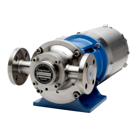
POLY-GUARD
SERIES
FLUOROPOLYMER-LINED, MAGNETIC-DRIVE,
CLOSE-COUPLED GEAR PUMPS
Models P1 thru P4
Models P5 thru P9
© May 2021 Liquiflo, All rights reserved
Document No.: 3.20.087
443 North Avenue, Garwood, NJ 07027 USA
Tel: 908-518-0777
Fax: 908-518-1847
www.liquiflo.com
Advertisement
Table of Contents

Related Manuals for Liquiflo POLY-GUARD Series


Summary of Contents for Liquiflo POLY-GUARD Series
- Page 1 & MAINTENANCE MANUAL ® POLY-GUARD SERIES FLUOROPOLYMER-LINED, MAGNETIC-DRIVE, CLOSE-COUPLED GEAR PUMPS Models P1 thru P4 Models P5 thru P9 © May 2021 Liquiflo, All rights reserved Document No.: 3.20.087 443 North Avenue, Garwood, NJ 07027 USA Tel: 908-518-0777 Fax: 908-518-1847 www.liquiflo.com...
-
Page 2: Table Of Contents
Liquiflo shall not be liable for damage or delays caused by a failure to follow the instructions for installation, operation and maintenance as outlined in this manual. -
Page 3: General Information
® Liquiflo Installation, Operation & Maintenance Manual Poly-Guard Series MAG-DRIVE Gear Pumps Models P1 thru P9, Close-Coupled Section 1: General Information General Instructions Series Mag-Drive, Close-Coupled Gear Pumps – Models P1 thru P9. ® This manual covers the Poly-Guard The materials of construction of the pump are selected based upon the chemical compatibility of the fluid being pumped. -
Page 4: Pump Specifications
® Liquiflo Installation, Operation & Maintenance Manual Poly-Guard Series MAG-DRIVE Gear Pumps Models P1 thru P9, Close-Coupled Pump Specifications ® Table 1: Poly-Guard Series MAG-DRIVE Gear Pump Specifications Pump Model Units ANSI 150# RFF 1-1/2 Port Size & Type DIN PN16 RFF... -
Page 5: Model Coding
® Liquiflo Installation, Operation & Maintenance Manual Poly-Guard Series MAG-DRIVE Gear Pumps Models P1 thru P9, Close-Coupled Model Coding ® Table 2: Model Coding for Poly-Guard Series Gear Pumps Position Description Code Selection Model P1 Pump Model P2 Pump 3/4” ANSI 150# / DN20 PN16... -
Page 6: Repair Kits & Replacement Parts
Standard Housings (No Bearing Flush) Repair Kits & Replacement Parts Repair kits and replacement parts for the pumps can be purchased from your local Liquiflo distributor. Refer to Appendices 2 and 3 for individual parts information. Returned Merchandise Authorization (RMA) -
Page 7: Safety Precautions
® Liquiflo Installation, Operation & Maintenance Manual Poly-Guard Series MAG-DRIVE Gear Pumps Models P1 thru P9, Close-Coupled Section 2: Safety Precautions General Precautions Always lock out the power to the pump driver when performing maintenance on the pump ... -
Page 8: Pump & Motor Installation
The pump inlet should be as close to the liquid source as practical and preferably below it. Even though gear pumps have self-priming and lift capability, many issues can be avoided with a flooded suction arrangement. NOTE: The Poly-Guard Series pumps are close-coupled and no alignment procedures between the pump and motor are required. General Piping Requirements Refer to the Hydraulic Institute Standards for piping guidelines. -
Page 9: Strainers & Solids Handling
Models P1 thru P9, Close-Coupled Strainers & Solids Handling Liquiflo gear pumps have very close internal clearances and are designed to pump relatively clean fluids. The entrance of foreign material could cause damage or rapid wear to pump components. While occasional small particles may not be catastrophic to the pump, the use of a strainer on the inlet will prevent large particulates from entering the pump. -
Page 10: Motor Hook-Up
The direction of rotation of the motor shaft (same as that of the pump drive shaft) will determine which side of the pump is the inlet (suction side) and which side is the outlet (discharge side). For the Poly-Guard Series pumps, the flow direction... -
Page 11: Start-Up & Operation
Refer to the performance curves of the specific pump model being operated (see Liquiflo website: www.liquiflo.com). During pump operation, inspect for: (1) Unusual noise, (2) Product leakage, (3) Expected suction and discharge pressures and (4) Expected flow rate based on pump speed, fluid viscosity and differential pressure. -
Page 12: Maintenance & Repair
® Liquiflo Installation, Operation & Maintenance Manual Poly-Guard Series MAG-DRIVE Gear Pumps Models P1 thru P9, Close-Coupled Section 5: Maintenance & Repair The pump has internal sleeve bearings, wear plates, gears and shafts, which require replacement over time due to physical wear. -
Page 13: Pump Disassembly
® Liquiflo Installation, Operation & Maintenance Manual Poly-Guard Series MAG-DRIVE Gear Pumps Models P1 thru P9, Close-Coupled PUMP DISASSEMBLY Follow the procedure below and refer to the Exploded View Drawing on page 27. 5.3.1 Cartridge Removal Remove the four sets of bolts (26), nuts (27) and lockwashers (28) that secure the front housing (15) to the pedestal (25). - Page 14 Plates NOTE: Steps are not necessary if you are using a Liquiflo Repair Kit to rebuild the pump. Remove the drive gear (4) and key (13) from the drive shaft (2) by removing the retaining ring(s) (5). Discard the retaining rings.
-
Page 15: Outer Magnet Removal
NOTE: The pedestal is shown connected directly to a motor, but the pedestal could also be connected directly to the Liquiflo S-Adapter (P/N SADAPT) or the Liquiflo Power Frame (P/N A-620804). Each of these devices can be used to long-couple the mag- drive pump to the motor. -
Page 16: Pump Assembly
(If required; see Note below.) NOTE: Steps 1 are not applicable if the gear-shaft components were supplied as part of a Liquiflo Repair Kit. (See chart on following page for repair kit Retaining components and Appendix 2 for additional parts information.) Ring... -
Page 17: Installation Of Bearings
® Liquiflo Installation, Operation & Maintenance Manual Poly-Guard Series MAG-DRIVE Gear Pumps Models P1 thru P9, Close-Coupled ® Poly-Guard Series Standard Repair Kit Components: Drive Gear-Shaft Assembly (1) Housing Alignment Pins (4) Idler Gear-Shaft Assembly (1) Housing O-Rings (2) Wear Plates (4) -
Page 18: Installation Of Wear Plates
NOTE: The drive shaft is located on the pump’s centerline. When the pump is in its normal horizontal orientation, the idler gear will be above the drive gear. Install the gear-shafts so that the Poly-Guard Series tag on the rear housing will be upright when the pump is horizontal. - Page 19 ® Liquiflo Installation, Operation & Maintenance Manual Poly-Guard Series MAG-DRIVE Gear Pumps Models P1 thru P9, Close-Coupled Place the remaining two wear plates (8) into the center housing (12) and on top of the gears, with the relief grooves facing down.
-
Page 20: Installation Of Inner Magnet
® Liquiflo Installation, Operation & Maintenance Manual Poly-Guard Series MAG-DRIVE Gear Pumps Models P1 thru P9, Close-Coupled While holding the front-center-rear housing assembly together, turn the assembly over to access the bolt holes on the rear housing (9). Install the housing bolts (16). -
Page 21: Installation Of Containment Can
® Liquiflo Installation, Operation & Maintenance Manual Poly-Guard Series MAG-DRIVE Gear Pumps Models P1 thru P9, Close-Coupled Lock the inner magnet (18) in place by installing the retaining ring (19) on the end of the drive shaft (2). Caution! Do not reuse Retaining Rings. -
Page 22: Outer Magnet-To-Motor Assembly
® Liquiflo Installation, Operation & Maintenance Manual Poly-Guard Series MAG-DRIVE Gear Pumps Models P1 thru P9, Close-Coupled 5.4.2 Outer Magnet-to-Motor Assembly The axial positioning of the outer magnet on the motor shaft is critical to pump performance. Improper positioning can cause the outer magnet to rub against the front housing or produce an axial load on the inner magnet, causing premature pump wear. -
Page 23: Outer Magnet Installation
® Liquiflo Installation, Operation & Maintenance Manual Poly-Guard Series MAG-DRIVE Gear Pumps Models P1 thru P9, Close-Coupled Outer Magnet Installation The procedure for installing the outer magnet on the motor shaft is dependent on the motor frame used with the pump. -
Page 24: Motor-To-Pedestal Assembly
® Liquiflo Installation, Operation & Maintenance Manual Poly-Guard Series MAG-DRIVE Gear Pumps Models P1 thru P9, Close-Coupled 5.4.3 Motor-to-Pedestal Assembly Install the motor (with outer magnet) to the pedestal (25) and bolt in place using four bolts (29). NOTE: The C-faces of the motor and pedestal should mate freely and mount flush. -
Page 25: Appendix
® Liquiflo Installation, Operation & Maintenance Manual Poly-Guard Series MAG-DRIVE Gear Pumps Models P1 thru P9, Close-Coupled Appendix 1: Fastener Torque Specifications Maximum Torque Specifications for 18-8 Stainless Steel Bolts BOLTS for PUMP-PEDESTAL ASSEMBLY: Max Torque Qty. Bolt Specifications Function... -
Page 26: Pump Parts List
For NEMA 56C thru 184TC motor frames. For bolts for IEC motor frames, see Appendix 1. NOTE: Reference Numbers above correspond to Reference Drawings on pages 27 and 28. For Liquiflo Part Numbers, refer to Poly-Guard Series Consolidated Bill of Materials (BOM). -
Page 27: Reference Drawings
® Liquiflo Installation, Operation & Maintenance Manual Poly-Guard Series MAG-DRIVE Gear Pumps Models P1 thru P9, Close-Coupled Appendix 3: Reference Drawings Exploded View Drawing – Poly-Guard ® Series Mag-Drive Gear Pump... - Page 28 Bolt, Adapter Plate (1/2-13 x 1 SHCS) * P8-P9: 5/16-18 X 4-1/2 SHCS * Item not shown. ** For NEMA motor frames. For bolts for IEC motor frames, see page 25. Note: For Liquiflo Part Numbers, refer to Poly-Guard Series Consolidated BOM.
- Page 29 ® Liquiflo Installation, Operation & Maintenance Manual Poly-Guard Series MAG-DRIVE Gear Pumps Models P1 thru P9, Close-Coupled Appendix 3: Reference Drawings (Continued) Dimensional Drawing #1 – Models P1 thru P4 with ANSI 150# Flanges BRACKET (PEDESTAL) Dimensional Drawing #2 – Models P5 thru P7 with...
- Page 30 ® Liquiflo Installation, Operation & Maintenance Manual Poly-Guard Series MAG-DRIVE Gear Pumps Models P1 thru P9, Close-Coupled Appendix 3: Reference Drawings (Continued) Dimensional Drawing #3 – Models P1 thru P4 with DIN PN16 Flanges BRACKET (PEDESTAL) Dimensional Drawing #4 – Models P5 thru P7 with...
- Page 31 ® Liquiflo Installation, Operation & Maintenance Manual Poly-Guard Series MAG-DRIVE Gear Pumps Models P1 thru P9, Close-Coupled Appendix 3: Reference Drawings (Continued) Dimensional Drawing #5 – Models P1 thru P4 with Universal ANSI 150# / DIN PN16 Flanges BRACKET (PEDESTAL) Dimensional Drawing #6 –...
-
Page 32: Troubleshooting Guide
® Liquiflo Installation, Operation & Maintenance Manual Poly-Guard Series MAG-DRIVE Gear Pumps Models P1 thru P9, Close-Coupled Appendix 4: Troubleshooting Guide Troubleshooting Guide - Part 1 Problem Possible Cause Corrective Action Verify suction pipe is submerged. Pump not primed Increase suction pressure. - Page 33 ® Liquiflo Installation, Operation & Maintenance Manual Poly-Guard Series MAG-DRIVE Gear Pumps Models P1 thru P9, Close-Coupled Appendix 4: Troubleshooting Guide (Continued) Troubleshooting Guide - Part 2 Problem Possible Cause Corrective Action Install suction strainer. Limit solids concentration. Abrasives in fluid Reduce pump speed or use larger pump running at lower speed.
- Page 34 ® Liquiflo Installation, Operation & Maintenance Manual Poly-Guard Series MAG-DRIVE Gear Pumps Models P1 thru P9, Close-Coupled NOTES...
- Page 35 ® Liquiflo Installation, Operation & Maintenance Manual Poly-Guard Series MAG-DRIVE Gear Pumps Models P1 thru P9, Close-Coupled NOTES...
Need help?
Do you have a question about the POLY-GUARD Series and is the answer not in the manual?
Questions and answers