Table of Contents
Advertisement
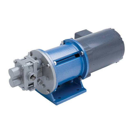
MAGNETIC-DRIVE, CLOSE-COUPLED GEAR PUMPS
H-SERIES: Models H1F, H3F, H5R, H5F, H7N, H7R, H7F, H9R & H9F
3-SERIES: Models 31F, 33F, 35R, 35F, 37R, 37F, 39R, 39F & 311F
© Jan. 2016 Liquiflo, All rights reserved
443 North Avenue, Garwood, NJ 07027 USA
TM
H-SERIES & 3-SERIES
Tel: 908-518-0777
INSTALLATION, OPERATION
& MAINTENANCE MANUAL
Fax: 908-518-1847
Document No.: 3.20.074
www.liquiflo.com
Advertisement
Table of Contents


Need help?
Do you have a question about the H-Series and is the answer not in the manual?
Questions and answers