Table of Contents
Advertisement
Quick Links
Advertisement
Table of Contents

Related Manuals for Lotus F45-78G


Summary of Contents for Lotus F45-78G
- Page 1 Installation and operating instructions PROFESSIONAL GAS FRYER F45-78G Model LIBR.ISTR.F45-78G Code 563015301 Review 1 Edition date 19/11/2018 Language English LOTUS S.p.A. Via Calmaor, 46 31020 San Vendemiano +39 0438 778020 +39 0438 778277 Translation of the original instructions...
-
Page 2: Table Of Contents
Contents Contents INTRODUCTION ......................... Installation drawing ........................Components..........................Example installation of the appliance................... GENERAL INFORMATION......................Declaration of compliance......................User information, RAEE Directive on waste electrical and electronic equipment ......Technical data table ........................INSTALLATION........................... Delivery checks ..........................Removing the packaging ......................Mechanical installation ......................... -
Page 3: Introduction
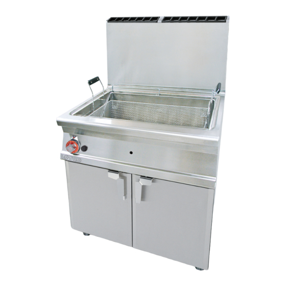
INTRODUCTION 1 INTRODUCTION Installation drawing FIG. 1 F45-78G A Data Plate B Electrical connection C Gas connection Translation of the original instructions... -
Page 4: Components
INTRODUCTION Components FIG. B 1 Thermostat knob 2 Green indicator light 3 White indicator light 4 Piezoelectric 5 Safety thermostat 6 Cap 7 Valve knob 8 Gas inlet 9 Valve 10 Ignition spark plug 11 Pilot 12 Extends drainage 13-14 Gas ramp 15 Injector 16 Oil drain Translation of the original instructions... - Page 5 INTRODUCTION FIG. C A Piezoelectric FIG. D 1 Bracket 2 Pilot light nozzle 3 Extends drainage 4 Ignition spark plug FIG. E Burner air adjustment Translation of the original instructions...
- Page 6 INTRODUCTION WIRING DIAGRAM F45-78G 1 Thermostat 2 Green indicator light 3 White indicator light 4 Power supply terminal board 5 Switch 6 Solenoid Translation of the original instructions...
-
Page 7: Example Installation Of The Appliance
INTRODUCTION Example installation of the appliance Translation of the original instructions... -
Page 8: General Information
GENERAL INFORMATION 2 GENERAL INFORMATION Declaration of compliance The manufacturer declares that the appliances comply with the requirements of the regulation GAR 2016/426 for the gas part and directive 2014/30/EU,2014/35/EU for the electrical part. Installation must be performed in compliance with current regulations, especially with regard to ventilation of the premises and the exhaust gas evacuation system. -
Page 9: User Information, Raee Directive On Waste Electrical And Electronic Equipment
Equipment) are those provided for by the national transpositions of European Directives 2012/19/EU Technical data table Technical data table F45 S70G RATED TOTAL RATED GAS FITTING TANK CAPACITY MODEL DIMENSIONS TOTAL GAS ELECTRICAL ISO 7-1 (lt) FLOW (kW) FLOW 230V~ F45-78G 80x70x90h R 3/4GM 0,005 Translation of the original instructions... -
Page 10: Installation
INSTALLATION 3 INSTALLATION Delivery checks On delivery, it is important to check the following: · External conditions of the packaging · The general status of the equipment · The conformity of the model with the information in the technical data plate and the instruction manual ·... - Page 11 INSTALLATION Warning Installation operations, any conversion to other types of gas and start-up must only be performed by qualified personnel, in accordance with current regulations. Gas systems, electrical connections and premises where the appliances are installed must comply with current regulations in the country of installation;...
- Page 12 INSTALLATION valve and fast-closing valve. Once installation is complete, make sure that there are no gas leaks from the fittings; to do this, do not use a naked flame but substances that do not cause corrosion, such as solutions of soapy water or leak detectors.
- Page 13 INSTALLATION - "A" type devices (see data plate) "A" type appliances must discharge combustion products into appropriate hoods, or similar devices, connected to an efficient fume stack or directly to the outside. (Natural evacuation) Fig. 1 If this is not possible, using an air suction device connected directly to the outside is permitted (Forced Evacuation) Fig.2, having a flow capacity not lower than the value defined in point 4.3 of the UNI-CIG 8723 standard.
- Page 14 INSTALLATION 1 Windproof fume stack (fig.3) - Extractor hood (fig.4) 2 Servo system "B11" type appliances are supplied on request with a hood or a hood and windproof fume stack to be assembled and delivered separately. Translation of the original instructions...
-
Page 15: Burners Technical Data Table (Itgb)
12.68 kWh/KG 12.87 kWh/KG 9.45 kWh/m3st. BUTANE PROPANE METHANE H 30 mbar 37 mbar 20 mbar F45-78G Burner injector 1/100 mm 8 x 120 8 x 120 8 x 180 Pilot injector 1/100 mm Consumption kg/h 3.470 kg/h 3.419... -
Page 16: Instructions For Use
INSTRUCTIONS FOR USE 5 INSTRUCTIONS FOR USE General information This appliance must only be used for its expressly intended purpose for cooking or heating food. Any other use is considered improper. The appliance is also intended for industrial use and must only be used by personnel trained for use and aware of the risks that the hot element entails. -
Page 17: Switching The Main Burner Off
INSTRUCTIONS FOR USE Switching the main burner off · Turn the graduated thermostat knob (fig. B pos.1) into position "0"; only the pilot burner flame remains ON Switching the appliance off · Press and turn the valve knob (fig. B pos.9) into position “0”. This command blocks the gas supply to the main burner and the pilot burner alike ... -
Page 18: Maintenance
MAINTENANCE 6 MAINTENANCE Routine When using the appliance over time, it is essential to perform regular maintenance to ensure safe operation. We therefore recommend stipulating a service contract. Caution Maintenance must only be performed by specialist personnel in compliance with current ... -
Page 19: Spare Parts
MAINTENANCE · Replace the nozzle with the appropriate version and make sure that, after ignition, the flame correctly touches the tip of the thermocouple Warning After conversion to another type of gas, update the technical data plate to indicate the type of ... -
Page 20: Cleaning
CLEANING 7 CLEANING Routine cleaning Caution The use of flammable fluids to clean the appliance is forbidden To ensure hygiene and the durability of the appliance, perform external cleaning on a regular basis, taking care not to damage the cables and the electrical connections. Before starting cleaning, disconnect the appliance from the power supply.
Need help?
Do you have a question about the F45-78G and is the answer not in the manual?
Questions and answers