Table of Contents
Advertisement
Quick Links
3003434-2014-04-14
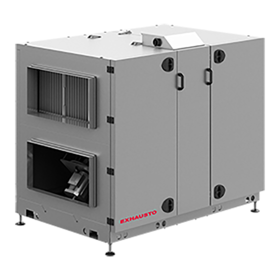
VEX260H
with rotary heat exchanger and EXact control system
Product information........................................Chapter 1 + 6
Mechanical assembly.....................................Chapter 2 + 3
Electrical installation.......................................Chapter 4
Maintenance...................................................Chapter 5
EXHAUSTO A/S
Odensevej 76
DK-5550 Langeskov
All manuals and user guides at all-guides.com
Tel. +45 65 66 12 34
Fax +45 65 66 11 10
exhausto@exhausto.dk
www.exhausto.dk
VEX260_EXact
Unit supplied with (factory fitted):
Compact filter FP
Filter bag FB
Trim damper and blowout zone,TB260
The following accessories are supplied
separately:
HCW external heating coil (water)
HCE external heating coil (electrical)
Closing damper, LS400x80024, (LSA exhaust)
Closing damper, LS400x80024, (LSF outdoor)
Closing damper, LSR400x80024, with
spring-return (LSFR outdoor)
pieces, Fire thermostat, BT40
pieces, Fire thermostat, BT50
pieces, Fire thermostat, BT70
pieces, HMI control panel
pieces, MIO-PIR motion sensor
pieces, MPT-DUCT constant pressure control
MIO-RH humidity sensor
MIO-CO2-ROOM, CO
-sensor
2
MIO-CO2-DUCT, CO
-sensor
2
MIO-TS-DUCT temperature sensor
MIO-TS-ROOM , temperature sensor
MXCU control for external cooling unit
Prod.order no.:
Sales order no.:
Original instructions
Advertisement
Table of Contents

Related Manuals for Exhausto VEX260H


Summary of Contents for Exhausto VEX260H
- Page 1 All manuals and user guides at all-guides.com VEX260_EXact 3003434-2014-04-14 VEX260H with rotary heat exchanger and EXact control system Unit supplied with (factory fitted): Compact filter FP Filter bag FB Trim damper and blowout zone,TB260 The following accessories are supplied separately:...
-
Page 2: Table Of Contents
All manuals and user guides at all-guides.com 3003434-2014-04-14 1. Product information 1.1. Model overview......................5 Model overview......................5 1.2. Terms used in these instructions................7 1.3. Application......................8 1.4. Location requirements..................8 1.4.1. Spatial requirements..................8 1.4.2. Requirements for underlying surface...............9 1.4.3. Requirements for duct system.................9 1.5. - Page 3 Scope This instruction manual is for use with EXHAUSTO VEX-type air handling units. Please refer to the product instructions regarding accessories and extra equipment. The instructions must be fully observed to ensure personal safety and to protect the equipment and ensure its correct operation.
- Page 4 ● Or use a padlock. Use the han- dle’s built-in padlock fixture Information plate The VEX unit information plate shows: ● VEX model type (1) ● Unit production no. (2) Have the production number ready at all times when contacting EXHAUSTO A/S. 4/34...
-
Page 5: Model Overview
All manuals and user guides at all-guides.com Product information 3003434-2014-04-14 1. Product information 1.1 Model overview Model overview Positioning of fan, Fan placement 1 (V1) motor (M) and fre- quency converter (FC) Fan placement 2 (V2) Elements Description Compact filter Bag filter 1,1,A or B Extract air spigot... - Page 6 All manuals and user guides at all-guides.com Product information 3003434-2014-04-14 Optional spigot positioning in relation to fan placement and filter type Compact filters Bag filters Fan placement and airflows Fan placement 1, Right Fan placement 1, Left Fan placement 2, Right Fan placement 2, Left 6/34...
-
Page 7: Terms Used In These Instructions
All manuals and user guides at all-guides.com Product information 3003434-2014-04-14 1.2 Terms used in these instructions The simplified diagram shows a VEX unit with LEFT fan placement. Component Function Fire thermostat, 40°C/50°C (extract air) BT40/BT50 Fire thermostat 70°C (supply air) BT70 Frequency converter 1 Frequency converter 2... -
Page 8: Application
Accessory. See checklist on the front page of these instructions. 1.3 Application Comfort ventilation EXHAUSTO VEX is used for comfort ventilation tasks. Operating temperature range for the unit – see section "Technical data". Prohibited uses The VEX unit is not to be used to transport solid particles or in areas where there is a risk of explosive gases. -
Page 9: Requirements For Underlying Surface
● heating/cooling losses Condensation Condensation in the ducts may occur when the exhaust/outdoor air has high hu- midity. EXHAUSTO recommends a condensation outlet is also fitted at the lowest point in the ducts. No duct connection If one or more of the spigots is not connected to a duct: Fit a... -
Page 10: Description
All manuals and user guides at all-guides.com Product information 3003434-2014-04-14 1.5 Description 1.5.1 The VEX unit design VEX200L - V1 The drawing below illustrates the construction of the unit (without service doors). 2,2,A 2,1,A 1,2,A 1,1,A 10/34... - Page 11 All manuals and user guides at all-guides.com Product information 3003434-2014-04-14 VEX200L - V2 1,2,A 1,1,A 2,1,A 2,2,A VEX200R - V1 The drawing below illustrates the construction of the unit (without service doors). 1,2,A 1,1,A 2,1,A 2,2,A 11/34...
- Page 12 All manuals and user guides at all-guides.com Product information 3003434-2014-04-14 VEX200R - V2 2,2,A 2,1,A 1,2,A 1,1,A Pos. no. Part Function Spigot, 2,1,A Outdoor air spigot. The spigot can also be positioned on the top or in the bottom of the unit (2,1,B) – though only on units with compact filters Closing damper (LS) Closing damper, outdoor air, LSF (accessory)
- Page 13 All manuals and user guides at all-guides.com Product information 3003434-2014-04-14 Pos. no. Part Function HMI panel Operation of the control system Fan unit For outdoor air/supply air Supply air fan frequency converter Variably adjusts fan Connection box Connection box for supply voltage, external ventilation com- ponents, control panels and PC connection Control system Positioning of control system components...
-
Page 14: Principal Dimensions
All manuals and user guides at all-guides.com Product information 3003434-2014-04-14 1.6 Principal dimensions VEX260, V1 1820 720,5 The base height is factory-set to 200 mm. The height can be adjusted between 150–240 mm. The drawing shows all of the spigot positioning options. Spigot positioning marked with * is not available for VEX units with a bag filter. -
Page 15: Vex260, V2
All manuals and user guides at all-guides.com Product information 3003434-2014-04-14 VEX260, V2 1820 720,5 The base height is factory-set to 200 mm. The height can be adjusted between 150–240 mm. The drawing shows all of the spigot positioning options. Spigot positioning marked with * is not available for VEX units with a bag filter. -
Page 16: Handling
All manuals and user guides at all-guides.com Handling 3003434-2014-04-14 2. Handling 2.1 Unpacking Supplied compo- The following components are supplied: ● VEX unit nents ● Supplied with accessories (as indicated in the checklist on the front page of the instructions) Packaging The unit is delivered attached to a disposable pallet and packed in clear plastic. -
Page 17: The Vex Sections' Principal Dimensions
All manuals and user guides at all-guides.com Handling 3003434-2014-04-14 2.2.2 The VEX sections' principal dimensions Measurements are based on the exact dimensions of the VEX unit. 2.2.3 Internal transport with reduced weight Weight reduction The weight can be reduced during transport by removing the service doors and fan units. - Page 18 All manuals and user guides at all-guides.com Handling 3003434-2014-04-14 Removing the serv- To remove the service doors: ice doors Detail A Detail B ● Open both doors ● Tap the hinge door pin out from below using a small pin bolt or similar ●...
- Page 19 All manuals and user guides at all-guides.com Handling 3003434-2014-04-14 To remove the fan unit Step Action Remove the fixing screws on the sliding rails (out towards the oper- ating side) Loosen the bindings on the motor cable and the measuring hose Pull the fan unit out to the end-stop (a screw on each rail acts as a stop) Remove the supply cable and modbus cable in the frequency con-...
-
Page 20: Mechanical Assembly
All manuals and user guides at all-guides.com Mechanical assembly 3003434-2014-04-14 3. Mechanical assembly 3.1 Installing the unit 3.1.1 Removal and assembly instructions The VEX unit is supplied mounted on its base. It may be removed, if necessary, to facilitate internal transport, as directed in this section. Step 1 Step 2 Step 3... - Page 21 All manuals and user guides at all-guides.com Mechanical assembly 3003434-2014-04-14 ● Open the four fittings (2) on the top of the VEX. Step 2, Top fittings ● Lift the fan sections and rotor section off the base. We recommend you place Step 3, VEX sections these sections on pallets for further transport.
- Page 22 All manuals and user guides at all-guides.com Mechanical assembly 3003434-2014-04-14 Step 4, Diagram showing levelling 1828 screw positions 1772 It is important that the base is level before the VEX unit is placed on it. Adjust the levelling screws, so that the base is horizontal (+/- 20 mm per metre) ●...
-
Page 23: Electrical Installation
All manuals and user guides at all-guides.com Electrical installation 3003434-2014-04-14 4. Electrical installation 4.1 Electrical installation See the attached instructions “Guide to Electrical Installation of VEX260/270 with EXact control system”: 23/34... -
Page 24: Maintenance
● EUROVENT certification is only valid if original filters are used ● Use of non-original filters may cause leakage in the VEX and impair filter func- tion ● EXHAUSTO recommends that you register the filter replacement date to en- sure filters are replaced at the correct intervals 24/34... -
Page 25: Service
All manuals and user guides at all-guides.com Maintenance 3003434-2014-04-14 5.3 Service 5.3.1 Filter replacement Use original filters Only use original filters. See section "Maintenance chart". How to replace fil- Disconnect power at the isolation switch before opening the ters door. Pull the filters out. - Page 26 All manuals and user guides at all-guides.com Maintenance 3003434-2014-04-14 Cleaning rotary ex- changer Step Action Switch off the power supply to the unit at the isolation switch before open- ing the doors Vacuum clean the exchanger with caution, ideally using a soft brush vac- uum nozzle Avoid touching the fins in the exchanger with sharp or hard objects –...
-
Page 27: Technical Data
All manuals and user guides at all-guides.com Technical data 3003434-2014-04-14 6. Technical data 6.1 Weight, corrosion class, temperature range, etc. Weights The total weight of the unit 525 kg Unit without doors, fan section and base (for internal transport) 361 kg Fan section (of which fan unit 2 x 33 kg) 2 x 117 kg Rotor section... - Page 28 All manuals and user guides at all-guides.com Technical data 3003434-2014-04-14 Motor damper Motor damper type LS400x800-24 LSR400x800-24 Term LSA/LSF LSFR Motor type NM24-F AF-24 Rotation time 75–150 s open: 150 s closed: 16 s Ingress protection IP42 IP42 Ambient temperature -20ºC to +50ºC -30ºC to +50ºC Damper depth (LS rail system)
-
Page 29: Compact Filters
All manuals and user guides at all-guides.com Technical data 3003434-2014-04-14 6.2 Compact filters Pressure loss graph for M5 and F7 filters Filter data FP260M5 FP260F7 Panel filter h x w qty. 2 650 x 575 mm qty. 2 650 x 575 mm Panel filter thickness 96 mm 96 mm... -
Page 30: Bag Filters
All manuals and user guides at all-guides.com Technical data 3003434-2014-04-14 6.3 Bag filters Pressure loss graph for M5 and F7 filters Filter data FB260M5 FB260F7 Filter area 1 x 2.5 m² 1 x 4.0 m² 1 x 3.0 m² 1 x 5.0 m² Face area (h x w) 1 x 592 x 490 mm 1 x 592 x 490 mm... -
Page 31: Capacity Diagram
All manuals and user guides at all-guides.com Technical data 3003434-2014-04-14 6.4 Capacity diagram 6.4.1 Unit with compact filter Capacity diagram with M5 filters SFP-curve (J/m ) Operating curves A: Pressure loss addition with F7 filters B: Pressure loss addition via external heating coil 31/34... -
Page 32: Unit With Bag Filter
Contact Contact your local EXHAUSTO office service department to order a spare part. The telephone number is shown on the back cover of these instructions. If required, see chapter 1, section "The VEX unit's design" for an overview of terms and of the po- sitions of parts. -
Page 33: Ec Declaration Of Conformity
All manuals and user guides at all-guides.com Technical data 3003434-2014-04-14 6.6 EC Declaration of Conformity See document no. 3003646, Declaration of Conformity. The document is found in the door of the VEX unit. It is also available on the EXHAUSTO website (search using document no.) 33/34... - Page 34 All manuals and user guides at all-guides.com...
Need help?
Do you have a question about the VEX260H and is the answer not in the manual?
Questions and answers