Canon imageFormula DR-9050C User Manual
Canon photo scanner user manual
Hide thumbs
Also See for imageFormula DR-9050C:
- Reference manual (68 pages) ,
- Maintenance manual (20 pages) ,
- Brochure & specs (4 pages)

Related Manuals for Canon imageFormula DR-9050C


Summary of Contents for Canon imageFormula DR-9050C
- Page 1 User Manual DR-9050C/DR-7550C DR-6050C Please read this manual before using the scanner. After you finish reading this manual, keep it in a safe place for future reference.
- Page 2 If such changes or modifications should be made, you could be required to stop operation of the equipment. Canon U.S.A. Inc. One Canon Plaza, Lake Success NY 11042, U.S.A. Tel. No. (516)328-5000 RADIO INTERFERENCE REGULATIONS (For 120 V models)
- Page 3 DR-9050C: Model M11068 Trademarks • Canon and the Canon logo are registered trademarks of Canon Inc. in the United States and may also be trademarks or registered trademarks in other countries. • imageFORMULA is a trademark of Canon Electronics Inc.
-
Page 4: Preface
Preface Thank you for purchasing the Canon imageFORMULA DR-6050C/DR-7550C/DR-9050C Document Scanner. Please read this and the following manuals thoroughly before using the scanner to become acquainted with its capabilities and make the most of its many functions. After reading the manuals, store them in a safe place for future reference. -
Page 5: Symbols Used In This Manual
Symbols Used in This Manual The following symbols are used in this manual to explain procedures, restrictions, handling precautions, and instructions that should be observed for safety. WARNING Indicates a warning concerning operations that may lead to death or injury to persons if not performed correctly. To use the scanner safely, always pay attention to these warnings. - Page 6 User Manual Hardware Please read this manual before using the scanner. After you finish reading this manual, keep it in a safe place for future reference.
-
Page 7: Table Of Contents
Table of Contents Preface ...iii Manuals for the Scanner ... iii Symbols Used in This Manual ... iv How This Manual is Organized...iv Chapter 1 Before You Start Using the Scanner 1. Important Safety Instructions...1-2 Installation Location... 1-2 Power ... 1-2 Moving the Scanner... - Page 8 3. Imprinter Ink Cartridge Replacement and Cleaning ...5-13 About the Imprinter ... 5-13 Replacing Ink Cartridges ... 5-13 Specifying the Printing Position ... 5-15 Cleaning the Imprinter ... 5-16 Imprinter Testing... 5-17 Chapter 6 Practical Examples 1. Messages ...6-2 Status Display... 6-2 Error Messages ...
- Page 9 Chapter 1 Before You Start Using the Scanner 1. Important Safety Instructions ... 1-2 Installation Location ...1-2 Power ...1-2 Moving the Scanner ...1-3 Handling ...1-3 Disposal ...1-5 2. Features... 1-6 3. Names and Functions of Parts ... 1-10 Front View, Feeder Inlet, and Eject Outlet ...1-10 Rear View...1-11 Control Panel ...1-12...
-
Page 10: Important Safety Instructions
Important Safety Instructions To ensure the safe operation of this scanner, be sure to read the safety warnings and precautions described below. Installation Location The performance of this scanner is affected by the environment in which it is installed. Make sure that the location where the scanner is installed meets the following environmental requirements. -
Page 11: Moving The Scanner
● If you have any questions regarding the power supply, contact your local authorized Canon dealer or service representative for further information. Moving the Scanner ● The scanner weights about 50 lbs (22.5 kg). - Page 12 OFF, and disconnect the power plug from the power outlet. Then, contact your local authorized Canon dealer or service representative to have the unit serviced. ■ Do not locate the scanner in a humid or dusty location.
-
Page 13: Disposal
■ Do not wear loose clothing or jewelry that may get caught in the scanner while you are using it. This may result in personal injury. Be extra careful of neckties and long hair. If anything becomes caught in the scanner, immediately disconnect the power cord to stop the scanner. -
Page 14: Features
Features The main features of the DR-6050C/7550C/9050C are described below. Scanner Features ● Variety of Scanning Modes The scanner is equipped with six scanning modes: Black and White, Error Diffusion, Advanced Text Enhancement, Advanced Text Enhancement II, 256- Color Grayscale, and 24-Bit Color. * Advanced Text Enhancement can clarify scanned text by processing background or foreground colors. - Page 15 Detection Functions ● Auto Image Type Detection The scanner automatically detects whether documents are in black and white or color. ● Auto Paper Size Detection The document page size is detected before scanning. Fixed-Size Scanning Auto-Size Detection ● Skew Detection The scanner stops feeding when a skewed document is detected as it touches the edge of the feeder inlet.
- Page 16 ● Deskew The scanner straightens an image when it recognizes from the image that the document page was fed askew. Skewed Image Deskewed Image ● Dropout and Color Enhancement The scanner is equipped with drop-out and enhancement functions that enable you to specify one color (red, blue, or green) to be omitted (dropped out) or enhanced when scanning, respectively.
- Page 17 Other Functions ● Rapid Recovery System When this function is activated and a sensor detects a misfeed due to a paper jam or double feed, which causes feeding to stop, scanning pauses to allow you to correct the cause of the misfeed, after which scanning continues from the document page on which the abnormality was detected.
-
Page 18: Names And Functions Of Parts
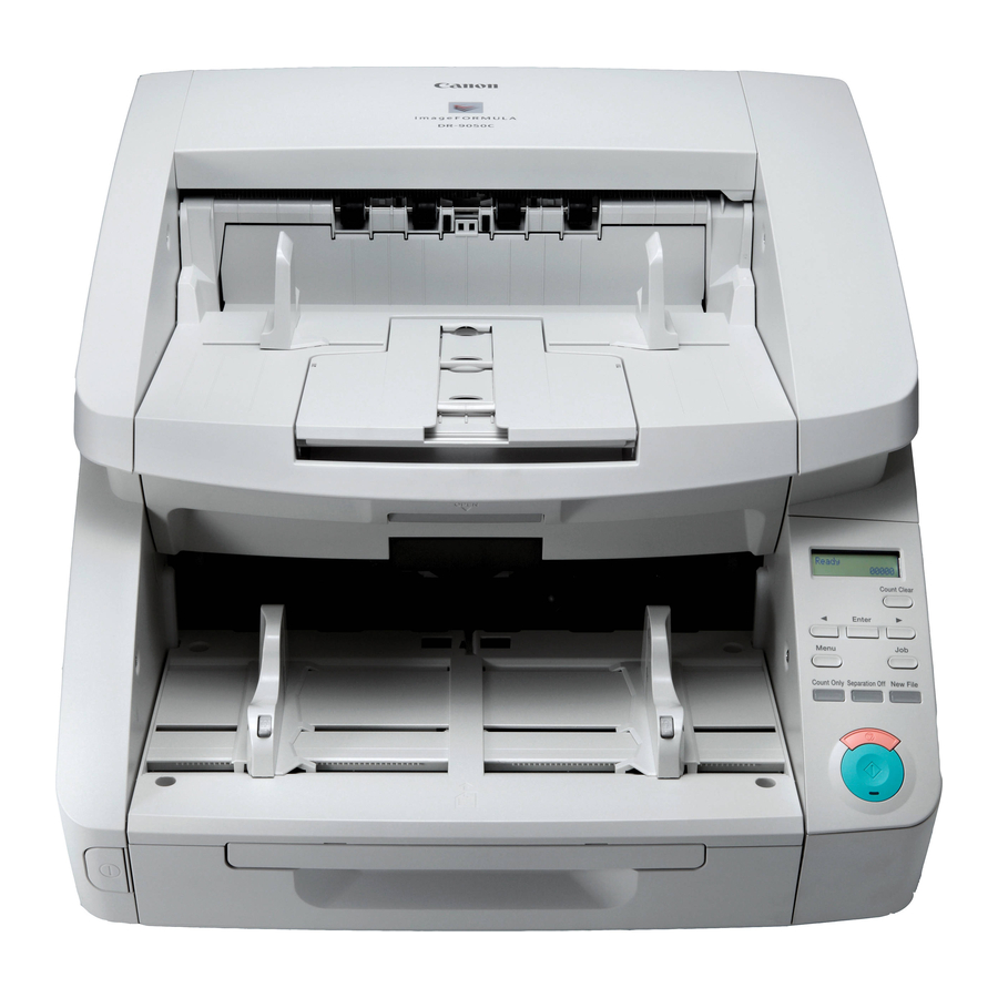
Names and Functions of Parts The names and functions of the DR-6050C/7550C/9050C parts are shown below. Front View, Feeder Inlet, and Eject Outlet Chapter 1 Before You Start Using the Scanner a Upper Unit Open when cleaning the rollers or paper jams. b Imprinter Cover Open when replacing the ink cartridge in the optional imprinter or when cleaning the imprinter. -
Page 19: Rear View
Rear View Chapter 1 Before You Start Using the Scanner a Ventilation Holes (Exhaust Fan) Exhausts heat from inside the scanner. b Power Connector Connect the supplied power cord here. c USB Connector (Type B) Connect the supplied USB cable here. d SCSI Connector (50-pin half-pitch D-sub receptacle) Connect the SCSI cable here. -
Page 20: Control Panel
Control Panel Chapter 1 Before You Start Using the Scanner a Display Panel Displays the user mode, job info, messages, and counter. b Count Clear Key Clears the counter on the display panel. c Enter Key Selects the user mode, and accepts settings. Keys Selects the user mode and job. -
Page 21: Chapter 2 Setup
Chapter 2 Setup 1. Setup Procedures ... 2-2 2. Installation Requirements ... 2-3 3. Software Installation ... 2-4 About the Setup Menu ...2-4 4. Connecting the Scanner to the Computer ... 2-6 Interface Connector Locations ...2-6 Connecting the Scanner to the Computer...2-6 5. -
Page 22: Setup Procedures
Setup Procedures Perform the following setup procedures to prepare the scanner for use. Step 1: Confirm the installation requirements. Step 2: Install the Software. (See p. 2-4) Step 3: Connect the scanner to the computer. Step 4: Turn the power ON (Scanner recognition). IMPORTANT •... -
Page 23: Installation Requirements
USB interface is USB Full-Speed (equal to USB 1.1). – Use the most recently available USB 2.0 driver provided by Microsoft. Contact your local authorized Canon dealer for more detailed information. – Not all USB interfaces provided as standard with personal computers are guaranteed. -
Page 24: Software Installation
Software Installation This section describes how to install the software. About the Setup Menu When you insert the included Setup disc into the computer’s CD drive, the menu shown below should appear. If the menu does not appear, use Explorer to access the CD drive and execute the file “SETUP.EXE”. - Page 25 Chapter 2 Setup ■ The Read Manual Screen From this screen you can select one of the supplied electronic manuals to read: the Easy Start Guide (a printed copy is also supplied), the Reference Guide, the User Manual (this manual), or the CapturePerfect 3.0 Operation Guide.
-
Page 26: Connecting The Scanner To The Computer
Connecting the Scanner to the Computer There are two methods for connecting the scanner to a computer: a USB connection to a standard USB port built in to the computer, or SCSI connection to a SCSI card installed in an expansion slot of the computer. Select the method that is best suited to your computer environment. - Page 27 Use the supplied USB cable to connect the scanner to the computer. Connect the square plug (Type B) of the USB cable to the scanner. Type B Type A ■ Using a SCSI Connection IMPORTANT Make sure that the computer is turned OFF before connecting the SCSI cable.
- Page 28 IMPORTANT Observe the following when connecting the scanner with other devices in a “daisy chain”. • The SCSI ID of the scanner is set to “SCSI ID = 2” by default. When using a daisy-chain configuration with other SCSI devices, set the DIP switches so that SCSI ID numbers are not duplicated in the system.
-
Page 29: Turning The Power On (Scanner Recognition)
Turning the Power ON (Scanner Recognition) When you turn ON the computer and the scanner, the Windows Plug and Play function recognizes the scanner and automatically installs the required device driver. About the Power Switch The power switch is located at the lower left side of the front of the scanner. - Page 30 • Windows Vista • The scanner is installed in Device Manager under [Imaging devices] as [CANON DR-XXXX USB] or [CANON DR-XXXX SCSI]. (XXXX varies depending on the model you are using) • From the Control Panel, you can display the Device Manager using the following procedure: –...
-
Page 31: Chapter 3 Basic Operation
Chapter 3 Basic Operation 1. Turning the Power ON and OFF... 3-2 About the Power Switch ...3-2 2. Documents... 3-3 Acceptable Documents ...3-3 3. Document Feed and Eject Trays ... 3-6 Preparing the Document Feed Tray...3-6 Adjusting the Document Guides...3-8 Preparing the Document Eject Tray ...3-10 4. -
Page 32: Turning The Power On And Off
Turning the Power ON and OFF Use the power switch to turn the scanner ON and OFF, or if you are using a USB connection, you can set the USB-linked power switch. CAUTION • After turning the scanner OFF, wait at least ten seconds before turning it back ON. •... -
Page 33: Documents
Documents The scanner can scan documents ranging in size from business cards and checks to 11" × 17"/A3 size. The size and type of paper that can be fed depends on the feeding method. Acceptable Documents The scanner can feed the following document sizes. Size Width: 2"... - Page 34 • Note that scanning the following types of documents can cause a paper jam or malfunction. To scan such a document, make a photocopy of the document and then scan the photocopy. Wrinkled or creased Carbon paper documents Curled documents Coated paper Extremely thin, Torn documents...
- Page 35 Confirm your settings. [ON2]: When the [Auto Detection] or [Scanner’s Maximum] page size setting is selected, document page lengths up to 118.11" (3 m) can be detected. [ON1]: When the [Auto Detection] or [Scanner’s Maximum] page size setting is selected, document page lengths up to 39.37"...
-
Page 36: Document Feed And Eject Trays
Document Feed and Eject Trays Before scanning, prepare the Document Feed and Eject Trays for the desired paper size. Preparing the Document Feed Tray ■ Document Feed Tray The height of the Document Feed Tray can be adjusted according to the number of document pages to be loaded (the default setting is the lowest position). - Page 37 Press [Enter]. Enter Key The current setting is indicated by blinking square brackets [ ]. Press the [ ] or [ ] key to select [0], [1] or [2]. Press [Enter] to accept the selection. The Document Feed Tray moves to the selected height. Press the Stop key to exit the User Mode.
-
Page 38: Adjusting The Document Guides
Gently open the extension wire. Hint Use the extension wire if the document extends beyond the edge of the document tray. Adjusting the Document Guides The document guides normally extend at equal distances from the left and right of the center of feeding so that your documents are centered in the feed inlet. - Page 39 Lock the right document guide (a), and unlock the left document guide (b). Slide the left document guide to the left edge of your documents. Chapter 3 Basic Operation ■ Resetting the Document Guides To reset the guides so that they are equidistant from the center, perform the following procedure to spread the guides to the left and right as far as they will go.
-
Page 40: Eject Paper Stoppers
Unlock the left document guide. Preparing the Document Eject Tray The Eject Tray includes two Document Eject Guides, the Eject Tray Extension and Eject Paper Stopper, to be adjusted to fit the width and length of your documents. ■ Document Guides Slide the document eject guides to fit the width of your documents. -
Page 41: Document Feeding Methods
Document Feeding Methods Two document feeding methods are available: Continuous Feeding, which feeds documents automatically from the document tray by the pickup roller; and Manual Feeding, which requires one document at a time to be positioned manually for transport by the feed roller, while the pickup roller is disabled. - Page 42 Continuous Manual Feeding Mode Enable the Continuous Manual Feeding Mode from the User Mode when document pages do not separate well using Continuous Feeding. Feed Roller Retard Roller IMPORTANT When the Continuous Manual Feeding Mode is set to ON from the User Mode, make sure to disable it (set to OFF) when finished scanning.
- Page 43 Press [Enter]. Enter Key The current setting is indicated by blinking square brackets [ ]. Press the [ ] or [ ] key to select [ON] or [OFF], and press [Enter] to accept the selection. Press the Stop key to exit the User Mode. Chapter 3 Basic Operation 3-13...
-
Page 44: Scanning
Scanning Scanning operations can be controlled by a scanning application program such as the CapturePerfect 3.0 software included with the scanner, or directly from the control panel of the DR-6050C/7550C/9050C, using the Job Function. This section describes the Job Function and provides an overview of CapturePerfect 3.0. About the Job Function The Job Function enables you to use the Job Registration Tool to register different jobs which can then be selected for... -
Page 45: Captureperfect 3.0
CapturePerfect 3.0 CapturePerfect 3.0 is an ISIS-compatible application developed for Canon document scanners. CapturePerfect 3.0 includes the following modes. Select the desired scan mode from the Scan menu to perform scanning. For more information on CapturePerfect 3.0, refer to the CapturePerfect 3.0 Operation Guide. -
Page 46: Using Captureperfect
Scan Job The scanning conditions and scan mode (Scan Batch to File, Scan Batch to Printer, or Scan Batch to Mail) are registered in advance as a job. The scan job can then be performed by selecting the registered job from the drop- down list (a) or by clicking (Scan Job) on the toolbar (b). - Page 47 Select [CANON DR-XXXX] and click [Settings]. (XXXX varies depending on the model you are using) IMPORTANT If [CANON DR-XXXX] is not displayed in the list of scanners, you must re-install the ISIS/TWAIN driver. Select the default page size and click [OK].
- Page 48 The Properties dialog box for the ISIS driver opens. Set the scan settings. Hint For more information on specifying the scan settings, TWAIN Driver Settings Dialog Box” on p. 8-4. Click the [OK] button to exit the scanner settings. Specify the file name and the file type for saving the image data.
- Page 49 • If the [Automatic Feeding] Feed Option is enabled, scanning is performed automatically whenever a sensor in the Document Feed Tray detects a loaded document, and pressing the Stop key causes the Continue Scanning dialog box to appear. • If the [Panel-Feeding] Feed Option is enabled, the Start key lamp is lit.
-
Page 50: Using Patchcode Sheets (Option)
Using Patchcode Sheets (Option) When the optional patchcode decoder is installed, the DR-6050C/7550C/9050C supports Automatic File Separation by detecting patchcode sheets inserted within a document, and performs batch separation. About Patchcode Sheets Patchcode patterns are printed on the patchcode sheets used to automatically separate files. -
Page 51: How To Use Patchcode Sheets
How to Use Patchcode Sheets This section describes how to use patchcode sheets with CapturePerfect 3.0. Print the patchcode sheets on a printer. IMPORTANT • Print (at original size) PATCH T (A4) and PATCH II (A4) sheets on A4 paper, or PATCH T (LTR) and PATCH II (LTR) on LTR paper. - Page 52 ■ Creating a Patchcode Sheet To copy a patchcode pattern to create a different size patchcode sheet, make sure to pay attention to the following precautions: IMPORTANT • Adjust the patchcode so that it fits into the effective area for detecting patchcode patterns.
-
Page 53: Clearing A Paper Jam Or Double Feed Error
Clearing a Paper Jam or Double Feed Error If a paper jam or double feed occurs during scanning, a paper jam message appears on the PC and on the scanner’s display panel. Use the following procedure to clear the paper jam. CAUTION •... -
Page 54: Handling A Double Feed
Check to verify the last saved image, and resume scanning. ■ When “Press Start Key” Appears When the Rapid Recovery System is enabled in the ISIS/ TWAIN driver settings, the following message appears on the display panel after you remove the jammed paper. IMPORTANT The Rapid Recovery System setting in the ISIS/TWAIN driver causes the following process to occur after a paper jam. - Page 55 IMPORTANT When a double feed is detected, the following process occurs, and messages appear according to the Rapid Recovery System setting in the ISIS/TWAIN driver. (See “[Rapid Recovery System] Check Box” on p. 8-18.) • When the Rapid Recovery System is disabled, images scanned before the double feed are saved as files, scanning finishes, and the following error message is displayed.
-
Page 56: Chapter 4 Other Functions
Chapter 4 Other Functions 1. Other Functions and Settings ... 4-2 2. Function Description ... 4-4 3. User Mode ... 4-8 User Mode Operating Procedure ...4-8 4. User Mode Functions... 4-10... -
Page 57: Other Functions And Settings
Other Functions and Settings The following DR-6050C/7550C/9050C functions are grouped together as Other Functions. For details, refer to the indicated pages. SCSI Speed USB Short Packet Imprinter (Optional) Imprinter Test Counter (Total Counter) Count (Roller Counter) Count-Only Mode Display Contrast Key Repeat Skew-Detection (Always On) Deskew... - Page 58 Hint • The Operation/Setting Methods are as follows: Panel Operation: The operation or setting is performed using the control panel keys. User Mode: The scanner function setting is made as a User Mode selection. ISIS/TWAIN: The function is an ISIS/TWAIN driver scanning setting. •...
-
Page 59: Count-Only Mode
Function Description The Other Functions are described below. See “User Mode” on p. ■ Count-Only Mode Counts the number of loaded document sheets by simply feeding them through the scanner. Hint The Count-Only mode is executed by the Count Only key on the control panel, and can be used to count document sheets even when no computer is connected. -
Page 60: Double-Feed Detection
Press the Start Key to start scanning. “Verifying…” is displayed. Hint If the specified count is exceeded while scanning, or if the scanned count does not reach the specified count when scanning is finished, an error is displayed. The specified count is exceeded while scanning Scanning finishes without reaching the specified count ■... -
Page 61: Staple Detection
■ Skew Detection If a long document page becomes skewed as it is fed, the page may press against the edge of the feed inlet or transport path and be damaged. When the scanner detects that a skewed page is contacting the edge of the transport path, an error message is displayed and transport stops. - Page 62 • Seam artifacts may appear in the reconstructed image because of the crease line or differences in the loading position of each side. • Load the document with the crease line on the right side. • The scan image of the front side becomes the left half of the reconstructed image.
-
Page 63: User Mode
User Mode The User Mode provides the user with the capability to change certain scanner functions. User Mode Operating Procedure User Mode operations are controlled by the following procedure. Hint Operating procedures differ according to User Mode function. For details, refer to the indicated pages. Press the Menu key on the control panel. - Page 64 Press [Enter]. Enter Key The current setting is indicated by blinking square brackets [ ]. Press the [ ] or [ ] key to select [ON2], [ON1] or [OFF], and press [Enter] to accept the selection. Press the [Stop] key to exit the User Mode. Chapter 4 Other Functions...
-
Page 65: User Mode Functions
User Mode Functions The following functions are available in the User Mode. ■ Buzzer (Beeper) Control Setting The beeper (“buzzer”) sounds when you press the control panel keys and when a scanning error occurs. ON2: The beeper sounds when a scanner error occurs, and when a control panel key is pressed. - Page 66 ■ Continuous Manual Feeding Mode Setting This mode disables automatic feeding by the pickup roller, so that the loaded document stack must be fed by hand one sheet at a time by the operator. (See “Continuous Manual Feeding Mode” on p. 3-12.) ON: The pickup roller is disabled.
- Page 67 ■ Key Repeat Setting Selects the panel display method. ON: The panel display scrolls when a key is pressed continuously. OFF: The panel display scrolls each time a key is pressed. Hint Key repeat is valid in the following situations. •...
-
Page 68: Chapter 5 Maintenance
Chapter 5 Maintenance 1. Regular Maintenance... 5-2 Cleaning the Scanner...5-2 Cleaning the Sensors...5-2 Cleaning the Scanning Glass and Rollers...5-3 Power Outlet ...5-4 2. Replacing the Transport Rollers ... 5-5 Roller Replacement Cycle...5-5 Checking and Resetting the Page Counter...5-5 Removing and Reinstalling the Rollers ...5-7 3. -
Page 69: Regular Maintenance
Regular Maintenance To maintain scanning quality, routinely clean the scanner as described below. CAUTION • Do not use spray cleaners to clean the scanner. Precision mechanisms may get wet and malfunction. • Never use paint thinner, alcohol, or other organic solvents to clean the scanner. Such solvents may deform or discolor the exterior of the scanner, and cause other damage. -
Page 70: Cleaning The Scanning Glass And Rollers
Scratches on the scanning glass may cause spots or streaks on scanned images, as well as feeding errors. If you find a scratch on the scanning glass, contact your local authorized Canon dealer or service representative to have the glass replaced. -
Page 71: Power Outlet
Wipe the rollers using a moistened and firmly wrung- out cloth while rotating the rollers. The rollers are located at the positions indicated in the figure below. Pickup Roller Feed Roller Transport Roller Platen Roller Retard Roller Remove the Pickup Roller, Feed Roller, and Retard Roller. -
Page 72: Replacing The Transport Rollers
■ Roller Replacement Kit The Roller Replacement Kit consists of replacement pickup, feed, and retard rollers. For details, contact your local authorized Canon dealer or service representative. Product Name: Roller Replacement Kit Product Code: 4009B001 Checking and Resetting the Page Counter The roller usage counter can be checked and reset using the Roller Counter in the User Mode setting. - Page 73 Press the Menu key on the control panel to activate the User Mode. Menu Key Press the [ ] key twice to display [Roller Counter]. Check the number of pages fed by the rollers, and press [Enter]. Enter Key The counter reset mode is activated. Press the [ ] key to select [RESET], and press [Enter].
-
Page 74: Removing And Reinstalling The Rollers
Removing and Reinstalling the Rollers Follow the procedure shown below to remove and reinstall the rollers when you need to clean or replace the Pickup, Feed, or Retard Rollers. CAUTION • Turn OFF the power switch, and disconnect the power plug from the power outlet when you remove or reinstall the rollers. - Page 75 Open the roller holder, and insert the new pickup roller. IMPORTANT Install the Pickup Roller so that side with the gear is on the left. Gear Close the roller cover. Check that it makes a latching sound and that it is securely returned to its original position.
- Page 76 Open the roller cover. Pull the roller lock lever down. Slide the feed roller to the right, and then pull them towards you. Remove the feed roller. Place the new feed roller on the pin. Put the feed roller in place (a), and align the notch in the roller’s axle with the shaft on the scanner (b).
- Page 77 Push the roller lock lever up to lock the feed roller. Close the roller cover. Check that it makes a latching sound and that it is securely returned to its original position. IMPORTANT Failure to firmly close the roller cover may cause a feed error. Always be sure to check that the roller cover is closed.
- Page 78 Grasp the roller cover with your fingers, and pull it up to remove it. Push the roller lock lever up (a) and move it to the left (b) to unlock the roller. Remove the retard roller. Set the retard roller into place in the scanner. Align the notches in the roller with the shaft pins in the scanner, then slide the roller lock lever in the direction indicated by the arrow.
- Page 79 Replace the roller cover. Push the front of the roller cover in. Check that it makes a latching sound and that it is securely returned to its original position. Gently lower the upper unit (a). Press down on both sides of the upper unit to ensure that it is securely closed (b).
-
Page 80: Imprinter Ink Cartridge Replacement And Cleaning
■ Preparing an Ink Cartridge Use one of the following red, blue or green HP ink cartridges. For details, contact your local authorized Canon dealer or service representative. Product Name: Ink Cartridge (Blue) Product Code: 3693A002 Product Name: Ink Cartridge (Red) - Page 81 Open the imprinter cover until it makes contact with the eject tray. Hint Perform the steps that follow with the imprinter cover fully open. Pull the lock lever outward (a) to release the ink cartridge lock (b). Remove the ink cartridge. Peel off the seal covering the nozzles of a new ink cartridge.
-
Page 82: Specifying The Printing Position
Push the ink cartridge as indicated by the arrow until it clicks into place. Adjust the carriage position by moving it left or right, then make sure you can feel it click in. “Specifying the Printing Position” on p. 5-15.) Positioning Holes (15 Locations) Hint... -
Page 83: Cleaning The Imprinter
Roughly align the right edge of the lock lever with the desired printing position. Hint The position of the right edge of the lock lever indicates the current printing position. Finely adjust the carriage position by moving it left or right, then make sure you can feel it click in. -
Page 84: Imprinter Testing
CAUTION Do not touch the metal contacts on the ink cartridge. Doing so may cause poor connections, resulting in poor print quality. Imprinter Testing After replacing an ink cartridge or cleaning the print head, perform a test print to confirm proper printing. Test printing is performed by the “Imprinter Test”... - Page 85 The Imprinter Test is enabled. Press the [ ] key to select [OK], and press [Enter]. The test print is executed. IMPORTANT If no paper is loaded for test printing, the imprinter test finishes without printing. Press the [Stop] key to exit the User Mode. 5-18 Chapter 5 Maintenance...
-
Page 86: Chapter 6 Practical Examples
Chapter 6 Practical Examples 1. Messages ... 6-2 2. Troubleshooting ... 6-5 3. Uninstalling the Software ... 6-9 Status Display ...6-2 Error Messages...6-3 Trouble Categories...6-5 Problem and Solution...6-5 Uninstalling the ISIS/TWAIN Driver...6-9... -
Page 87: Messages
Messages There are two types of display panel messages: “status indicator messages” and “error messages” that appear when the scanner encounters a problem. Status Display The following messages appear on the display panel to indicate the scanner’s operating state: ■ Counting... Status: Operating in Count-Only mode. -
Page 88: Error Messages
Problem: Internal scanner error. Solution: Turn the power OFF, and restart the scanner. If this does not solve the problem, make a note of the error code, and contact your Canon service representative. ■ Skew Detected Error Code: J018 Problem: A skewed document page contacted the wall of the transport path. - Page 89 ■ Double Feed Error Code: D002 Problem: A double feed was detected by the document length. Solution: Remove the double fed document page(s), return them to the Document Feed Tray, and scan again. (See p. 3-24.) Error Code: D004 Problem: A double feed was detected ultrasonically. Solution: Remove the double fed document page(s), return them to the Document Feed Tray, and scan again.
-
Page 90: Troubleshooting
• Scanning Results Are Not as Expected (See p. 6-7) It you cannot resolve a problem, contact your local authorized Canon dealer or your service representative. Problem and Solution ■ The Scanner Does Not Turn ON If the scanner does not turn ON, first confirm the following: ✔... - Page 91 If this does not solve the problem, consider the following possible causes: Cause The SCSI card is not compatible with the scanner. Solution Use a recommended SCSI card. Cause The scanner’s SCSI ID is identical to the SCSI ID of another device. Solution Check the SCSI IDs of all SCSI devices connected to the system and set a unique SCSI...
- Page 92 • Replacement rollers can be purchased as consumables. If performance is not improved after cleaning the rollers, contact your local Canon dealer or service representative to purchase a Roller Replacement Kit, and replace the rollers (pickup, feed and retard rollers).
- Page 93 If lines still appear on the image even after you clean the scanning glass and rollers, the scanning glass inside the scanner may be scratched. Contact your local authorized Canon dealer or service representative. Problem The scanned image is abnormal for certain documents. Cause...
-
Page 94: Uninstalling The Software
Uninstalling the Software Some scanner malfunctions can be resolved by reinstalling the software. Before reinstalling the software, make sure to completely uninstall any previous installation first. Uninstalling the ISIS/TWAIN Driver The following procedure uses the ISIS/TWAIN driver as an example. Follow the same procedure to uninstall the Job Registration Tool and CapturePerfect 3.0. - Page 95 Click the [Continue] button. The file-deletion confirmation screen appears. Click [Yes] to proceed with uninstallation. When uninstallation is finished, click [Finish]. Chapter 6 Practical Examples 6-10...
- Page 96 Chapter 7 Appendix 1. Specifications... 7-2 Unit Specifications...7-2 Options...7-3 Consumables ...7-3 External Dimensions ...7-4 2. Option Specifications ... 7-5 Barcode Specifications...7-5 Imprinter Specifications...7-6 3. Index ... 7-7...
-
Page 97: Chapter 7 Appendix 1. Specifications
200 dpi Duplex 120 images/min. 150 images/min. 170 images/min. 300 dpi Other Double-Feed Detection, Deskew, User Mode, Long Document Mode, and Folio Scan Chapter 7 Appendix DR-9050C 90 pages/min. 90 pages/min. DR-9050C 90 pages/min. 90 pages/min. DR-9050C 90 pages/min. 90 pages/min. -
Page 98: Options
If this happens, replace the rollers, regardless of the page count. • For information about the roller replacement kit, contact your local authorized Canon dealer or service representative. Ink Cartridge: Blue (Product Code: 3693A002) This blue ink cartridge is used by the imprinter. -
Page 99: External Dimensions
Chapter 7 Appendix External Dimensions 20.91" (531 mm) 23.62" (600 mm) 28.27" (718 mm) -
Page 100: Option Specifications
Option Specifications This section contains the specifications for the separately sold Barcode Module Sheets (Option)” (p. 3-20) for the specifications of the patchcodes that can be detected by the patchcode decoder. Barcode Specifications The following barcodes can be read by installing the optional barcode module. -
Page 101: Imprinter Specifications
Item Condition Position Feeding At least 0.079" (2 mm) from Direction the edge of the page Perpendicular At least 0.197" (5 mm) from to Feeding the edge of the page Direction Quantity Up to four per page Spacing At least 0.197" (5 mm) Conditions No background or overlapping barcodes Imprinter Specifications... -
Page 102: Index
Index CapturePerfect 3.0 ... 3-15 Cleaning glass ... 5-3 power outlet ... 5-4 print heads ... 5-16 rollers ... 5-3 scanner ... 5-2 sensors ... 5-2 Cleaning Cloth ... 5-2 Connecting to a Computer ... 2-6 Control Panel ... 1-12 Counter ... - Page 103 Safety Instructions ... 1-2 Scanner Recognition ... 2-9 Scanning ... 3-14 SCSI Connection ... 2-7 SCSI Connector ... 2-6 Setup ... 2-2 Setup Menu ... 2-4 custom installation ... 2-4 read manuals ... 2-5 typical installation ... 2-4 Skew Detection ... 4-6 Software installing ...
- Page 104 User Manual Software Please read this manual before using the scanner. After you finish reading this manual, keep it in a safe place for future reference.
- Page 105 Table of Contents Chapter 8 ISIS/TWAIN Driver Settings 1. Before You Start Using the Scanner ...8-2 2. ISIS/TWAIN Driver Settings Dialog Box ...8-4 [Basic] Tab Sheet ... 8-6 [Brightness] Tab Sheet ... 8-14 [Image processing] Tab Sheet... 8-16 [Others] Tab Sheet ... 8-18 [Imprinter/Addon] Tab Sheet ...
- Page 106 Chapter 8 ISIS/TWAIN Driver Settings 1. Before You Start Using the Scanner... 8-2 2. ISIS/TWAIN Driver Settings Dialog Box ... 8-4 [Basic] Tab Sheet...8-6 [Brightness] Tab Sheet...8-14 [Image processing] Tab Sheet ...8-16 [Others] Tab Sheet...8-18 [Imprinter/Addon] Tab Sheet ...8-25...
-
Page 107: Chapter 8 Isis/Twain Driver Settings
The [Select Scanner] dialog box opens. Select [CANON DR-XXXX], and click [Settings]. (XXXX varies depending on the model you are using) IMPORTANT If [CANON DR-XXXX] does not appear, try reinstalling the ISIS/ TWAIN driver. Select the default page size and click [OK]. - Page 108 IMPORTANT • Clicking the [Default] in the ISIS Driver Properties dialog box, the setting is applied here. • For the TWAIN driver, the default paper size is LTR/A4 and cannot be changed. Click [OK] to finish scanner selection. Chapter 8 ISIS/TWAIN Driver Settings...
-
Page 109: Isis/Twain Driver Settings Dialog Box
ISIS/TWAIN Driver Settings Dialog Box If menus or buttons are selected to configure the scanner settings from an application tool such as CapturePerfect 3.0 or the Job Registration Tool, the following ISIS/TWAIN Driver Settings dialog box is displayed. The ISIS/TWAIN Driver Settings dialog box consists of the standard tab sheets [Basic], [Brightness], [Image processing], [Others], and [Imprinter/Addon]. - Page 110 • [Basic] Tab Sheet (See p. 8-6) • [Brightness] Tab Sheet (See p. 8-14) Chapter 8 ISIS/TWAIN Driver Settings • [Image processing] Tab Sheet (See p. 8-16) • [Others] Tab Sheet (See p. 8-18)
-
Page 111: [Basic] Tab Sheet
• [Imprinter/Addon] Tab Sheet (See p. 8-25) Buttons [OK] button Applies the settings and closes the dialog box. Hint When you use an application program that scans from the TWAIN Driver Settings dialog box, [Scan] is displayed instead of [OK] to scan with the configured settings. Dialog Box”... - Page 112 [Basic] Tab Advanced Version (ISIS driver only) This [Basic] tab sheet is displayed when the DR-6050C/ 7550C/9050C ISIS Driver is utilized from a scanner setting or scanning dialog box belonging to an ISIS- compatible application program. This tab sheet contains settings for the scanner functions that are not supported in the dialog box belonging to the application program.
- Page 113 [Auto Color Detection] The document is detected as black-and-white or color before the scanned image is saved. Selecting this mode enables the [Setting] button for opening the [Auto Image Type Detection Settings] dialog box, where you can make settings for auto image type detection.
- Page 114 Dots per inch Select the scanning resolution. Hint • Higher resolutions provide clearer images, but produce larger files. • The [Moire Reduction] setting is enabled when the resolution is set to 300 dpi or lower, and the [Image Quality] setting is enabled when the resolution is set to 400 or 600 dpi.
- Page 115 Moire Reduction This setting is enabled when the resolution is set to 300 dpi or lower. Use Moire reduction if the Moire (a shimmering, wavy pattern) effect appear in scanned images. Hint [High-Speed Moire Reduction] is displayed when the resolution is set to 240 dpi or lower.
- Page 116 [Area] button Open the [Scan Area] dialog box to specify the area to scan. (See “[Scan Area] Dialog Box” on p. 8-12.) IMPORTANT The [Area] button is not displayed if the application program provides its own function to specify the scan area. ■...
- Page 117 Brightness and Contrast Adjust the brightness and contrast when [Advanced Text Enhancement] or [Advanced Text Enhancement II] is selected for [Mode in case of binary]. For other modes, the brightness and contrast are set on the [Brightness] tab sheet. ■ [Scan Area] Dialog Box In this dialog box you can define the area of the document page to scan on a selected page size, and register non- standard document page sizes.
- Page 118 Page Size This setting is linked to the [Page Size] setting, for selecting the size of the document pages to scan. Hint Clicking the [Custom] button opens the [Custom Page Size] dialog box, where non-standard page sizes can be registered as custom page sizes.
-
Page 119: [Brightness] Tab Sheet
[Brightness] Tab Sheet On the [Brightness] tab sheet you can adjust brightness and contrast for scanning, and access gamma settings. The availability of brightness and contrast settings depends on the mode setting of the [Basic] tab sheet. Hint If all of the settings on the [Brightness] tab sheet are disabled, the gamma setting is set to Custom. - Page 120 • When the [Auto] check box is selected, the slider automatically selects a brightness level to be used for automatic adjustment. Contrast Adjusts the contrast of images to be scanned. [Enable Back Side Brightness] Check Box If the brightness of the front and back of the document pages is different, select this check box to adjust only the brightness of the back side.
-
Page 121: [Image Processing] Tab Sheet
Hint • Click any point in the Gamma Curve Graph to set that point as an output value. • Drag the mouse on the Gamma Curve Graph to set the output value according to the mouse movement. [Import] button Clicking this button loads the gamma table data (*.pxg) that was previously stored with the [Export] button. - Page 122 Document Orientation Specify a rotation angle to correct the orientation of images. Hint Scanned images are rotated as follows, according to the orientation of loaded documents and the selected angle. Feeder Document: Face Up Document Orientation 0 degrees 90 degrees 180 degrees (Clockwise) Output...
-
Page 123: [Others] Tab Sheet
Color drop-out These selections are enabled for scanning modes other than 24-bit Color, so that you can select a primary color (red, green, blue) or gray to be ignored (dropped out) or enhanced. The [Setting] buttons are enabled when [Drop-out color Custom] or [Custom Color Enhance] is selected, so that you can specify a color range in the [Color Settings] dialog box for drop-out or enhancement. - Page 124 [Staple Detection] Check Box Select this check box to stop feeding when the sensor detects a folded corner on a document, which occurs when an attempt is made to feed stapled documents. Detection” on p. 4-6.) [JPEG Transfer] Check Box When this check box is selected, scanned image data is always compressed to JPEG format within the scanner for output to the computer.
- Page 125 IMPORTANT If the documents overlap by less than 1.97" (50 mm), or if the documents cling (such as from static electricity), ultrasonic detection of double feeds may not word correctly. Feeding Option You can select the feeding method for document scanning. [Standard Feeding] Load a document and then start scanning with an application program.
- Page 126 [Panel-Feeding] or [Automatic Feeding] Feeding Option [Auto] Each batch of documents is saved with different file names. [Panel] A batch is separated when you press the [New File] key on the control panel to start or continue scanning. Batch Separation (when a patchcode decoder is installed) When the optional patchcode decoder is installed, batch separation by patchcode is enabled for all feeding option...
- Page 127 [Prescan] Check Box When this check box is selected, the first document page is prescanned and displayed in the Prescan panel when scanning is first started. Continue scanning after you confirm or adjust brightness and contrast of the scanned image in the Prescan window. [Verify Count] Check Box When this check box is selected, the count from the scanner’s count-only mode or an optionally set count is...
- Page 128 [Search Side] Select the side(s) of the document on which to detect barcodes. [Search Front] Detect barcodes on the front side of documents. [Search Back] Detect barcodes on the back side of documents. [Barcodes per Page] Sets the number of barcodes (1 to 4) to detect per page. [Orientation] Set the orientation of the barcodes to detect.
- Page 129 [Checksum] Read the checksum included in barcodes. [Output Checksum] This check box is enabled when [Checksum] is selected, and outputs the read checksum. [Output ST/SP] Select this check box to output Start and Stop codes. Codabar Detect Codabar barcodes. [Enable] Detect and read Codabar barcodes.
-
Page 130: [Imprinter/Addon] Tab Sheet
[Output Header] Select this check box to output header codes. Hint • To detect barcodes with and without add-on codes at the same time, select [Auto] for the addon setting before scanning. • When the barcode type is unknown, enable detection of all types (Auto Detect), and deselect the Checksum boxes before scanning. - Page 131 [Single counter with number of characters] abbreviation: <Cx> A dialog box appears in which to specify the number of characters of the single counter. A counter of the specified number of characters will be imprinted or added on scanned images. [Double counter with number of characters] abbreviation: <CxCx>...
- Page 132 Orientation Specify the orientation of characters to be imprinted or added. Hint Text orientation relative to the feeding direction is as follows. Orientation 0 degrees 90 degrees 180 degrees Print Imprinter Font Specify the font size of characters to be imprinted or added.
- Page 133 ■ [First Counter] and [Second Counter] Dialog Boxes Make settings for add-on counters. [Start Value] Enter the start value for the counter. [Increment] Enter the increment value for the counter. The counter increases by the value entered here. [Increment Trigger] Specifies the type of event that triggers a counter increment.
-
Page 134: Chapter 9 Job Registration Tool Settings
Chapter 9 Job Registration Tool Settings 1. Before Use... 9-2 Job Function...9-2 Starting the Job Registration Tool...9-2 2. Job Registration Tool... 9-3 3. Settings Dialog Boxes... 9-5 [New/Editing] Dialog Box...9-5 [Admin] Dialog Box...9-8... -
Page 135: Before Use
Follow the procedure below to start the Job Registration Tool. Click the [Start] button, and then click [All Programs] - [Canon DR-XXXX] - [Job Registration Tool]. (XXXX varies depending on the model you are using) Chapter 9 Job Registration Tool Settings “About the Job Function”... -
Page 136: Job Registration Tool
Job Registration Tool The Job Registration Tool consists of the main window below and the [New/Editing] and [Admin] dialog boxes. For details on the dialog boxes, see the description of each dialog box. Menu Bar [Editing] Menu Select a job from the job list, and register a new job or edit, copy, or delete the job. - Page 137 Job List Displays the job numbers (01 to 99) and job titles. Job Information Displays the information for the job selected in the job list. [Close] Button Ends the Job Registration Tool. Chapter 9 Job Registration Tool Settings...
-
Page 138: Settings Dialog Boxes
Settings Dialog Boxes The settings dialog boxes of the Job Registration Tool include the [New/Editing] dialog box and [Admin] dialog box. For details, see the description of each dialog box. Hint “About the Job Function” on p. 3-14 for the procedure for executing jobs registered by the Job Registration Tool. [New/Editing] Dialog Box In the [New/Editing] dialog box, you can register new jobs and edit registered jobs. - Page 139 Scanner Settings Press the [Setting] button to configure scanner settings. [Save to Pictures folder] Check Box Select this check box to save image files to the Pictures folder of the user logged in to Windows. Hint • The name displayed for Pictures differs depending on the name of the folder in the Windows you are using.
- Page 140 [Access setting] Button This button is enabled when the [Save to Pictures folder] check box is not selected, and allows you to enter the user name and password required to access the shared network folder specified for [Save in folder]. IMPORTANT Access to shared network folders may be restricted to users with certain access permission.
-
Page 141: [Admin] Dialog Box
[Compression] Check Box Select this check box to compress images saved to files. Black and white (binary) images are compressed in CCITT Group 4 format, and grayscale and color images in JPEG format. When this check box is not selected, the saved files are much larger. - Page 142 [Warning Size] Enter the maximum total size for all files saved to the specified folder. IMPORTANT • When saving to removable storage media such as CD-R, specify the maximum capacity of the media. • When folder monitoring ([Display Warning Dialog]) is enabled, a warning message appears when starting to scan if the total size of the files in the specified folder exceeds the specified limit.
-
Page 143: Chapter 10 Practical Examples
Chapter 10 Practical Examples 1. About Basic Condition Settings ... 10-2 Confirming the Basic Conditions for Scanning...10-2 2. Practical Examples ... 10-4 Scanning Documents of Unregistered Page Sizes ...10-4 Specifying the Scanning Area ...10-5 Configuring Scanner Settings According to the Purpose...10-6 Registering Your Settings ...10-11... -
Page 144: About Basic Condition Settings
About Basic Condition Settings This chapter provides an overview of the basic setting items that are the minimum requirements when configuring the scanner settings. For details on settings, see Chapter 8 “ISIS/TWAIN Driver Settings Dialog Confirming the Basic Conditions for Scanning When you scan a document, be sure to confirm the basic conditions [Mode], [Page Size], [Dots per inch], and... -
Page 145: Practical Examples
Scanning Side Select which page side(s) to scan. Hint • If the scanning side is set to [Skip blank page], the images of blank pages are deleted when the images are saved. • [Folio] recombines the front and back images scanned from both sides of the document into a single image. -
Page 146: Practical Examples
Practical Examples This section provides an overview of which items to set according to the purpose when configuring the scanning settings. For details on settings, see Chapter 8 “ISIS/TWAIN Driver Settings Dialog Scanning Documents of Unregistered Page Sizes Configuring the following settings allows you to scan a document of an unregistered page size. -
Page 147: Page Sizes
■ Scanning documents wider than the feeder inlet (Folio Scan) When you want to scan a document that is wider than the feeder inlet, you can scan the document if you fold the document into two, load it into the feed tray, and set the scanning side setting to [Folio]. -
Page 148: Configuring Scanner Settings According To The Purpose
Hint • With the TWAIN driver, load the document you want to specify the area of and press the [Preview] button to scan the document and display the preview image in the Area panel. You can then specify the area from the displayed preview image. - Page 149 ■ When you want to skip or enhance intermediate colors Select an intermediate color in [Color drop-out] on the [Image processing] tab sheet. Click the [Setting] button to display the Color Settings dialog box, and then you can specify the color range of the intermediate colors to ignore (drop out) or enhance.
- Page 150 ■ When you want to change the brightness on the front and back sides to scan a document with front and back sides of different densities Set the brightness of the back side on the [Brightness] tab sheet. (See p. 8-15.) Hint The brightness of the back side cannot be changed when you are using advanced text enhancement for scanning.
- Page 151 ■ When you want to save black and white images and color images separately when scanning a mixture of black and white documents and color documents When documents are scanned while the mode is set to [Auto Color Detection] on the [Basic] tab sheet, the document colors are detected and black and white images and color images are saved separately.
- Page 152 ■ When you want to remove the black spots from scanned images when scanning documents with punch holes Select [Punch Hole Removal] on the [Image processing] tab sheet. The black spots from punch holes in documents are removed from scanned images. (See p.
-
Page 153: Registering Your Settings
■ When you want to delete the images of the blank pages in two-sided documents If you set the scanning side setting to [Skip blank page] on the [Basic] tab sheet, the images of blank pages in the document are deleted. (See p. - Page 154 CANON ELECTRONICS INC. 1248, SHIMOKAGEMORI, CHICHIBU-SHI, SAITAMA 369-1892, JAPAN CANON U.S.A. INC. ONE CANON PLAZA, LAKE SUCCESS, N.Y. 11042, U.S.A. CANON CANADA INC. 6390 DIXIE ROAD, MISSISSAUGA, ONTARIO L5T 1P7, CANADA CANON EUROPA N.V. BOVENKERKERWEG 59-61, P.O.BOX 2262, 1180 EG AMSTELVEEN, THE NETHERLANDS CANON LATIN AMERICA, INC.
Need help?
Do you have a question about the imageFormula DR-9050C and is the answer not in the manual?
Questions and answers