
Related Manuals for HID VertX V1000


Summary of Contents for HID VertX V1000
-
Page 1: Quick Start, Vertx (Cs) V1000
9292 Jeronimo Road Irvine, CA 92618-1905 Quick Installation Guide V1000 ACCESS CONTROLLER © 2006 HID Global Corporation. All rights reserved. Document Version 1.4 October 5, 2006 Document Number 6080-904B.5... -
Page 2: Table Of Contents
..........................14 Firewall ............................16 Central Station Automation Providers .................... 16 Contact Information ..........................17 Configuration Checklist - Static and Modem ..................19 Installation Worksheet ..........................A1 October 2006 Page 2 of 20 © 2006 HID Global Corporation. All rights reserved. -
Page 3: Introduction
Input Circuits * 500 feet (150 m) (18AWG), or equivalent. 2-conductor, using ALPHA 1172C (22AWG) or Alpha 1897C (18AWG), Output Circuits * 500 feet (150 m) or equivalent. October 2006 Page 3 of 20 © 2006 HID Global Corporation. All rights reserved. -
Page 4: Overview
+12 VDC IN * Minimum wire gauge depends on cable length and current requirements. Ove r vie w The following outlines what is required to install the V1000. October 2006 Page 4 of 20 © 2006 HID Global Corporation. All rights reserved. -
Page 5: Step 1 Connect
Connect one end of the Cat5 network patch cable to the J1 (RJ-45) connector on the V1000 and the other end to the network connection point (network jack, hub, switch, or router) on your site. October 2006 Page 5 of 20 © 2006 HID Global Corporation. All rights reserved. - Page 6 Connect the Tamper input to a tamper switch on Bat Fail + the enclosure. AC Fail - AC Fail + Tamper - Tamper + October 2006 Page 6 of 20 © 2006 HID Global Corporation. All rights reserved.
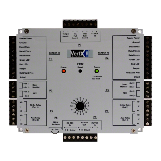
- Page 7 If the RS-485 is wired In and Out, and power is lost, or the P9 terminal block is unplugged on a V100-Series panel, RS-485 communications will be lost to downstream V100- Series panels. October 2006 Page 7 of 20 © 2006 HID Global Corporation. All rights reserved.
- Page 8 1K – 6K Ohm. The setup of supervised inputs should be done during configuration of the VertX devices via the central station automation software (host). October 2006 Page 8 of 20 © 2006 HID Global Corporation. All rights reserved.
- Page 9 P4 Pins 2/1 P5 Pins 6/5 P5 Pins 4/3 P5 Pins 2/1 P7 Pins 8/7 Tamper P7 Pins 6/5 AC Fail P7 Pins 4/3 Batt Fail October 2006 Page 9 of 20 © 2006 HID Global Corporation. All rights reserved.
-
Page 10: Modem
M ode m Se t u p Re qu ir e m e n t s • External Modem (not included). The modem must be selected from the following approved HID modem list: o Zoom V.90 56 K Fax Modem, Model 2949 (external modem uses phone jack) o U.S. -
Page 11: Step 2 Contact
Blink OFF 5. Click Configure Unit to open the Basic Configuration page of that controller 6. Go to Step 3 Configure, page 12 October 2006 Page 11 of 20 © 2006 HID Global Corporation. All rights reserved. -
Page 12: Virtual Port
Choices include: • Network • Modem • Network with Modem Backup Default network information will load. Before making changes, review the default network information. October 2006 Page 12 of 20 © 2006 HID Global Corporation. All rights reserved. - Page 13 Verify that the changes submitted are accurate, and click Save . If the changes submitted are not accurate, click Cancel adjust the settings appropriately. October 2006 Page 13 of 20 © 2006 HID Global Corporation. All rights reserved.
-
Page 14: Step 4 Communicate
Configure provides the ability to view and modify system inputs and outputs and door characteristics. Upon successful validation, the Save button will write modified values to the interface board. October 2006 Page 14 of 20 © 2006 HID Global Corporation. All rights reserved. - Page 15 3. After the LED turns amber, remove the jumper from the P9 debug port. Upon removing the jumper it takes approximately 60 seconds for the controller to reset. Once the reset is complete, the LED will return to green. October 2006 Page 15 of 20 © 2006 HID Global Corporation. All rights reserved.
-
Page 16: Firewall
(default) to the new parameter. 5. Click Submit and the change will become activated once the controller is rebooted. 6. Close the browser window(s) when completed. October 2006 Page 16 of 20 © 2006 HID Global Corporation. All rights reserved. -
Page 17: Contact Information
HI D Asia Pacific Lt d. ( Hong Kong) support : support _APAC@hidvert x.com sales: salesapac@hidvert x.com t elephone: ( 852) 3160 9802 fax num ber: ( 852) 3160 4809 October 2006 Page 17 of 20 © 2006 HID Global Corporation. All rights reserved. - Page 18 Connect the equipment into an outlet on a circuit different from that to which the receiver is connected. • Consult the dealer or an experienced radio/TV technician for help. October 2006 Page 18 of 20 © 2006 HID Global Corporation. All rights reserved.
-
Page 19: Configuration Checklist - Static And Modem
TCP/IP Connection Port TCP/IP Listen Port Login Password Modem Modem Type Incoming Mode CS/Host Phone Number VertX RS-232 Port Modem CS Host (IP Address or Host Name) October 2006 Page 19 of 20 © 2006 HID Global Corporation. All rights reserved. - Page 20 VertX V1000 (CS) Quick Installation Guide Intentional Blank October 2006 Page 20 of 20 © 2006 HID Global Corporation. All rights reserved.
-
Page 21: Installation Worksheet
Relay 1: Relay 2: Relay 3: Relay 4: Relay 5: Relay 6: Relay 7: Relay 8: Relay 9: Relay 10: Relay 11: Relay 12: Input 1: Input 2: October 2006 Page A1 © 2006 HID Global Corporation. All rights reserved. - Page 22 Relay 2: Relay 1: Relay 2: Relay 3: Relay 4: Relay 5: Relay 6: Relay 7: Relay 8: Relay 9: Relay 10: Relay 11: Relay 12: Input 1: Input 2: October 2006 Page A2 2006 © HID Global. All rights reserved.
Need help?
Do you have a question about the VertX V1000 and is the answer not in the manual?
Questions and answers